This catalog is out of date, see note on page 2
Bus converter unit UI
Description and ordering data
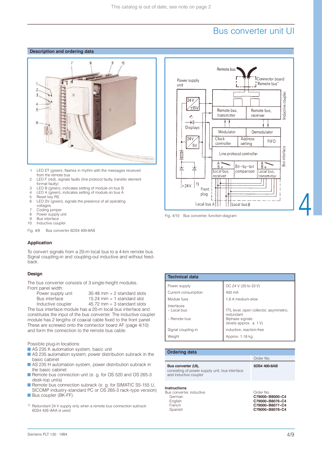
1LED ET (green), flashes in rhythm with the messages received
from the remote bus
2LED F (red), signals faults (line protocol faulty, transfer element
format faulty)
3LED B (green), indicates setting of module on bus B
4 LED A (green), indicates setting of module on bus A 5 Reset key RS
6 LED SV (green), signals the presence of all operating voltages
7 Coding jumper
8 | Power supply unit | Fig. 4/10 Bus converter, function diagram | |
9 | Bus interface | ||
| |||
10 | Inductive coupler |
|
Fig. 4/9 Bus converter 6DS4 400-8AB
Application
To convert signals from a
Design
The bus converter consists of 3
Power supply unit | 30.48 mm = 2 standard slots |
Bus interface | 15.24 mm = 1 standard slot |
Inductive coupler | 45.72 mm = 3 standard slots |
The bus interface module has a
Possible
![]() AS 235 K automation system, basic unit
AS 235 K automation system, basic unit
![]() AS 235 automation system, power distribution subrack in the basic cabinet
AS 235 automation system, power distribution subrack in the basic cabinet
![]() AS 235 H automation system, power distribution subrack in the basic cabinet
AS 235 H automation system, power distribution subrack in the basic cabinet
![]() Remote bus connection unit (e. g. for OS 520 and OS
Remote bus connection unit (e. g. for OS 520 and OS
![]() Remote bus connection subrack (e. g. for SIMATIC
Remote bus connection subrack (e. g. for SIMATIC ![]() Bus coupler
Bus coupler
1)Redundant 24 V supply only when a remote bus connection subrack 6DS4
Technical data |
|
Power supply | DC 24 V (20 to 33 V) |
Current consumption | 450 mA |
Module fuse | 1.6 A |
Interfaces | TTL level, open collector, asymmetric, |
- Local bus | |
- Remote bus | redundant |
Biphase signals | |
| (levels approx. 1 V) |
Signal | inductive, |
Weight | Approx. 1.18 kg |
|
|
Ordering data
|
| Order No. |
Bus converter (UI), |
| 6DS4 |
consisting of power supply unit, bus interface |
|
|
and inductive coupler |
|
|
|
|
|
Instructions |
|
|
Bus converter, inductive |
| Order No |
German |
| |
English |
| |
French |
| |
Spanish |
|
Siemens PLT 130 . 1994 | 4/9 |