This catalog is out of date, see note on page 2
Mode of operation
Addressing, transmission modes
This method has the following important advantages:
![]() There is far less loading on the bus system since only the information is read from the automation system which is cur- rently displayed on the monitor channels
There is far less loading on the bus system since only the information is read from the automation system which is cur- rently displayed on the monitor channels
![]() Data need only be stored at one position as a result of the distributed data base principle. Modifications are therefore only necessary at one position
Data need only be stored at one position as a result of the distributed data base principle. Modifications are therefore only necessary at one position
![]() No special planning for the OS systems is required in the automation systems (exception: curve display)
No special planning for the OS systems is required in the automation systems (exception: curve display)
![]() Acces to information in the automation systems by another computer is possible without additional planning (by using the function ”Read parameters”).
Acces to information in the automation systems by another computer is possible without additional planning (by using the function ”Read parameters”).
The cyclic data exchange is also used for a life test of all partici- pants connected to the CS 275 bus by an OS operation and monitoring system. Each failure and also the return of a partici- pant is supervised and signalled.
Sporadic data transfer
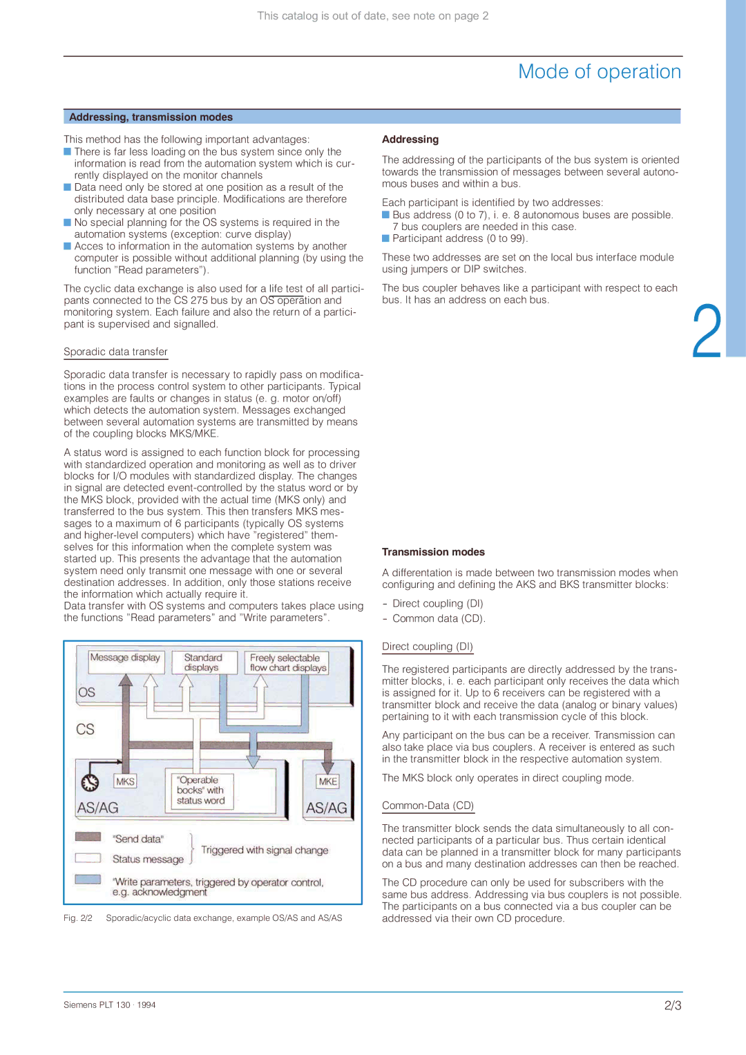
Sporadic data transfer is necessary to rapidly pass on modifica- tions in the process control system to other participants. Typical examples are faults or changes in status (e. g. motor on/off) which detects the automation system. Messages exchanged between several automation systems are transmitted by means of the coupling blocks MKS/MKE.
A status word is assigned to each function block for processing with standardized operation and monitoring as well as to driver blocks for I/O modules with standardized display. The changes in signal are detected
Data transfer with OS systems and computers takes place using the functions ”Read parameters” and ”Write parameters”.
Fig. 2/2 Sporadic/acyclic data exchange, example OS/AS and AS/AS
Addressing
The addressing of the participants of the bus system is oriented towards the transmission of messages between several autono- mous buses and within a bus.
Each participant is identified by two addresses:
![]() Bus address (0 to 7), i. e. 8 autonomous buses are possible. 7 bus couplers are needed in this case.
Bus address (0 to 7), i. e. 8 autonomous buses are possible. 7 bus couplers are needed in this case.
![]() Participant address (0 to 99).
Participant address (0 to 99).
These two addresses are set on the local bus interface module using jumpers or DIP switches.
The bus coupler behaves like a participant with respect to each bus. It has an address on each bus.
Transmission modes
A differentation is made between two transmission modes when configuring and defining the AKS and BKS transmitter blocks:
Direct coupling (DI)
The registered participants are directly addressed by the trans- mitter blocks, i. e. each participant only receives the data which is assigned for it. Up to 6 receivers can be registered with a transmitter block and receive the data (analog or binary values) pertaining to it with each transmission cycle of this block.
Any participant on the bus can be a receiver. Transmission can also take place via bus couplers. A receiver is entered as such in the transmitter block in the respective automation system.
The MKS block only operates in direct coupling mode.
The transmitter block sends the data simultaneously to all con- nected participants of a particular bus. Thus certain identical data can be planned in a transmitter block for many participants on a bus and many destination addresses can then be reached.
The CD procedure can only be used for subscribers with the same bus address. Addressing via bus couplers is not possible. The participants on a bus connected via a bus coupler can be addressed via their own CD procedure.
Siemens PLT 130 . 1994 | 2/3 |