This catalog is out of date, see note on page 2
Interface module for 20-m local bus (N-BK)
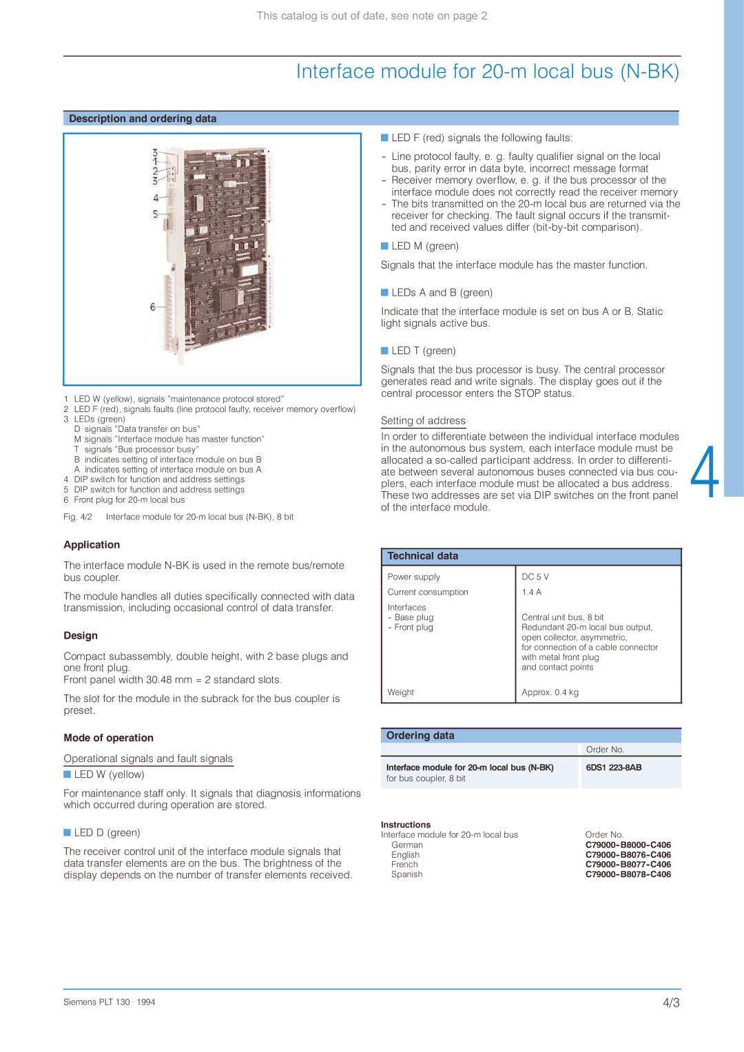
Description and ordering data
1 LED W (yellow), signals ”maintenance protocol stored”
2LED F (red), signals faults (line protocol faulty, receiver memory overflow)
3 LEDs (green)
D signals ”Data transfer on bus”
M signals ”Interface module has master function” T signals ”Bus processor busy”
B indicates setting of interface module on bus B A indicates setting of interface module on bus A
4 DIP switch for function and address settings
5 DIP switch for function and address settings
6 Front plug for
Fig. 4/2 Interface module for 20-m local bus (N-BK), 8 bit
Application
The interface module
The module handles all duties specifically connected with data transmission, including occasional control of data transfer.
Design
Compact subassembly, double height, with 2 base plugs and one front plug.
Front panel width 30.48 mm = 2 standard slots.
The slot for the module in the subrack for the bus coupler is preset.
Mode of operation
Operational signals and fault signals
![]() LED W (yellow)
LED W (yellow)
For maintenance staff only. It signals that diagnosis informations which occurred during operation are stored.
![]() LED D (green)
LED D (green)
The receiver control unit of the interface module signals that data transfer elements are on the bus. The brightness of the display depends on the number of transfer elements received.
![]() LED F (red) signals the following faults:
LED F (red) signals the following faults:
![]() LED M (green)
LED M (green)
Signals that the interface module has the master function.
![]() LEDs A and B (green)
LEDs A and B (green)
Indicate that the interface module is set on bus A or B. Static light signals active bus.
![]() LED T (green)
LED T (green)
Signals that the bus processor is busy. The central processor generates read and write signals. The display goes out if the central processor enters the STOP status.
Setting of address
In order to differentiate between the individual interface modules in the autonomous bus system, each interface module must be allocated a
Technical data |
|
|
|
| |
Power supply |
| DC 5 V |
|
| |
Current consumption |
| 1.4 A |
|
| |
Interfaces |
| Central unit bus, 8 bit |
| ||
- Base plug |
|
| |||
- Front plug |
| Redundant |
| ||
|
| open collector, asymmetric, |
| ||
|
| for connection of a cable connector |
| ||
|
| with metal front plug |
| ||
|
| and contact points |
| ||
Weight |
| Approx. 0.4 kg |
|
| |
|
|
|
|
|
|
|
|
|
|
| |
Ordering data |
|
|
|
| |
|
|
|
| Order No. |
|
Interface module for |
| 6DS1 |
| ||
for bus coupler, 8 bit |
|
|
|
| |
|
|
|
|
| |
Instructions |
|
|
|
| |
Interface module for |
|
| Order No. |
| |
German |
|
|
| ||
English |
|
|
| ||
French |
|
|
| ||
Spanish |
|
|
| ||
Siemens PLT 130 . 1994 | 4/3 |