This catalog is out of date, see note on page 2
Interface module for 20-m local bus (N16-M), 16 bit
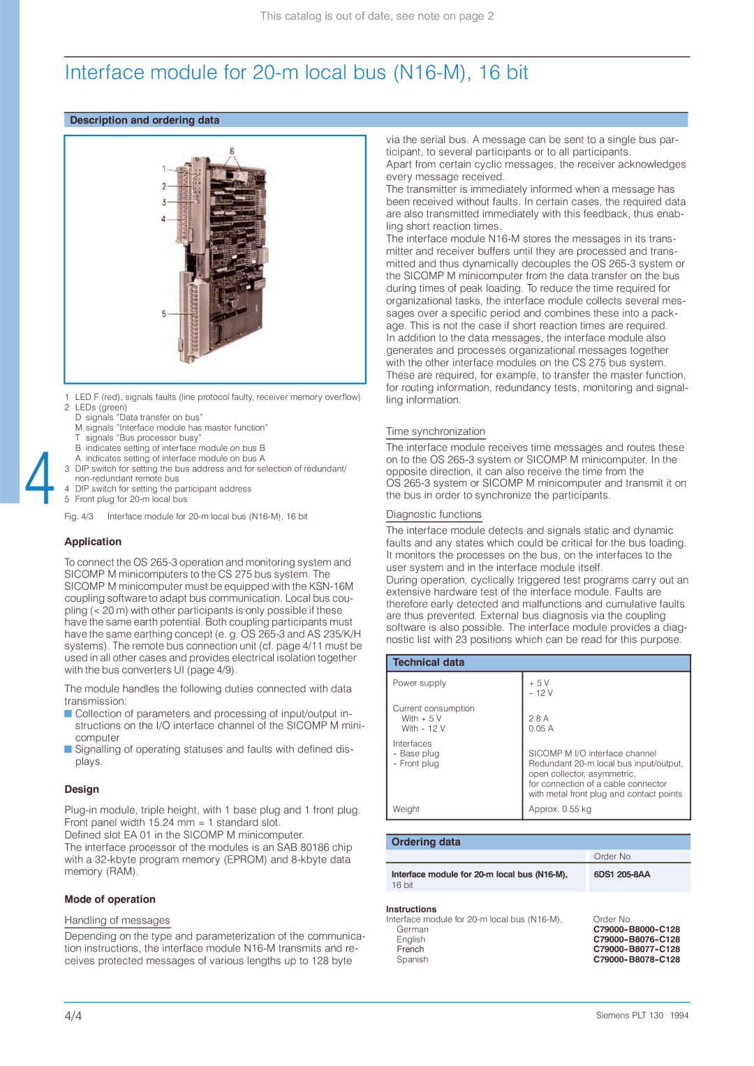
Description and ordering data
1LED F (red), signals faults (line protocol faulty, receiver memory overflow)
2 LEDs (green)
D signals ”Data transfer on bus”
M signals ”Interface module has master function” T signals ”Bus processor busy”
B indicates setting of interface module on bus B A indicates setting of interface module on bus A
3 DIP switch for setting the bus address and for selection of redundant/
4 DIP switch for setting the participant address
5 Front plug for
Fig. 4/3 Interface module for 20-m local bus (N16-M), 16 bit
Application
To connect the OS
The module handles the following duties connected with data transmission:
![]() Collection of parameters and processing of input/output in- structions on the I/O interface channel of the SICOMP M mini- computer
Collection of parameters and processing of input/output in- structions on the I/O interface channel of the SICOMP M mini- computer
![]() Signalling of operating statuses and faults with defined dis- plays.
Signalling of operating statuses and faults with defined dis- plays.
Design
Defined slot EA 01 in the SICOMP M minicomputer.
The interface processor of the modules is an SAB 80186 chip with a
via the serial bus. A message can be sent to a single bus par- ticipant, to several participants or to all participants.
Apart from certain cyclic messages, the receiver acknowledges every message received.
The transmitter is immediately informed when a message has been received without faults. In certain cases, the required data are also transmitted immediately with this feedback, thus enab- ling short reaction times.
The interface module
In addition to the data messages, the interface module also generates and processes organizational messages together with the other interface modules on the CS 275 bus system.
These are required, for example, to transfer the master function, for routing information, redundancy tests, monitoring and signal- ling information.
Time synchronization
The interface module receives time messages and routes these on to the OS
OS
Diagnostic functions
The interface module detects and signals static and dynamic faults and any states which could be critical for the bus loading. It monitors the processes on the bus, on the interfaces to the user system and in the interface module itself.
During operation, cyclically triggered test programs carry out an extensive hardware test of the interface module. Faults are therefore early detected and malfunctions and cumulative faults are thus prevented. External bus diagnosis via the coupling software is also possible. The interface module provides a diag- nostic list with 23 positions which can be read for this purpose.
Technical data
Power supply | + 5 V |
| - 12 V |
Current consumption | 2.8 A |
With + 5 V | |
With - 12 V | 0.05 A |
Interfaces | SICOMP M I/O interface channel |
- Base plug | |
- Front plug | Redundant |
| open collector, asymmetric, |
| for connection of a cable connector |
| with metal front plug and contact points |
Weight | Approx. 0.55 kg |
|
|
Ordering data
|
| Order No. |
Interface module for |
| 6DS1 |
16 bit |
|
|
Mode of operation
Handling of messages
Depending on the type and parameterization of the communica- tion instructions, the interface module
Instructions |
|
Interface module for | Order No. |
German | |
English | |
French | |
Spanish |
4/4 | Siemens PLT 130 . 1994 |