This catalog is out of date, see note on page 2
Bus coupler
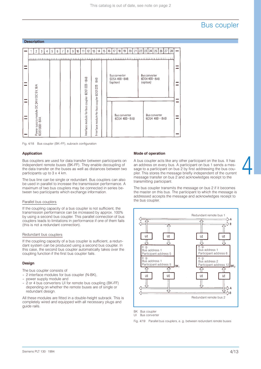
Description
Fig. 4/18 Bus coupler (BK-FF), subrack configuration
Application
Bus couplers are used for data transfer between participants on independent remote buses
The bus line can be single or redundant. Bus couplers can also be used in parallel to increase the transmission performance. A maximum of two bus couplers may be connected in series be- tween two participants which exchange information.
Parallel bus couplers
If the coupling capacity of a bus coupler is not sufficient, the transmission performance can be increased by approx. 100% by using a second bus coupler. This parallel connection of bus couplers leads to limitations in performance if one of them fails (this is not a redundant connection).
Redundant bus couplers
If the coupling capacity of a bus coupler is sufficient, a redun- dant system can be produced using a second bus coupler. In this case, the second bus coupler automatically takes over the coupling function if the first bus coupler fails.
Design
The bus coupler consists of
All these modules are fitted in a
Mode of operation
A bus coupler acts like any other participant on the bus. It has an address on every bus. A participant on bus 1 sends a mes- sage to a participant on bus 2 by first addressing the bus cou- pler. This stores the message briefly independent of the current message transfer on bus 2 and acknowledges receipt to the transmitting participant.
The bus coupler transmits the message on bus 2 if it becomes the master on this bus. The participant to which the message is addressed accepts the message and acknowledges receipt to the bus coupler.
Redundant remote bus 1
e. g. | e. g. |
Bus address 1 | Bus address 1 |
Participant address 5 | Participant address 6 |
e. g. | e. g. |
Bus address 1 | Bus address 2 |
Participant address 5 | Participant address 12 |
Redundant remote bus 2
BK Bus coupler
UI Bus converter
Fig. 4/19 Parallel bus couplers, e. g. between redundant remote buses
Siemens PLT 130 . 1994 | 4/13 |