This catalog is out of date, see note on page 2
Interface module for 20-m local bus (N-V.24)
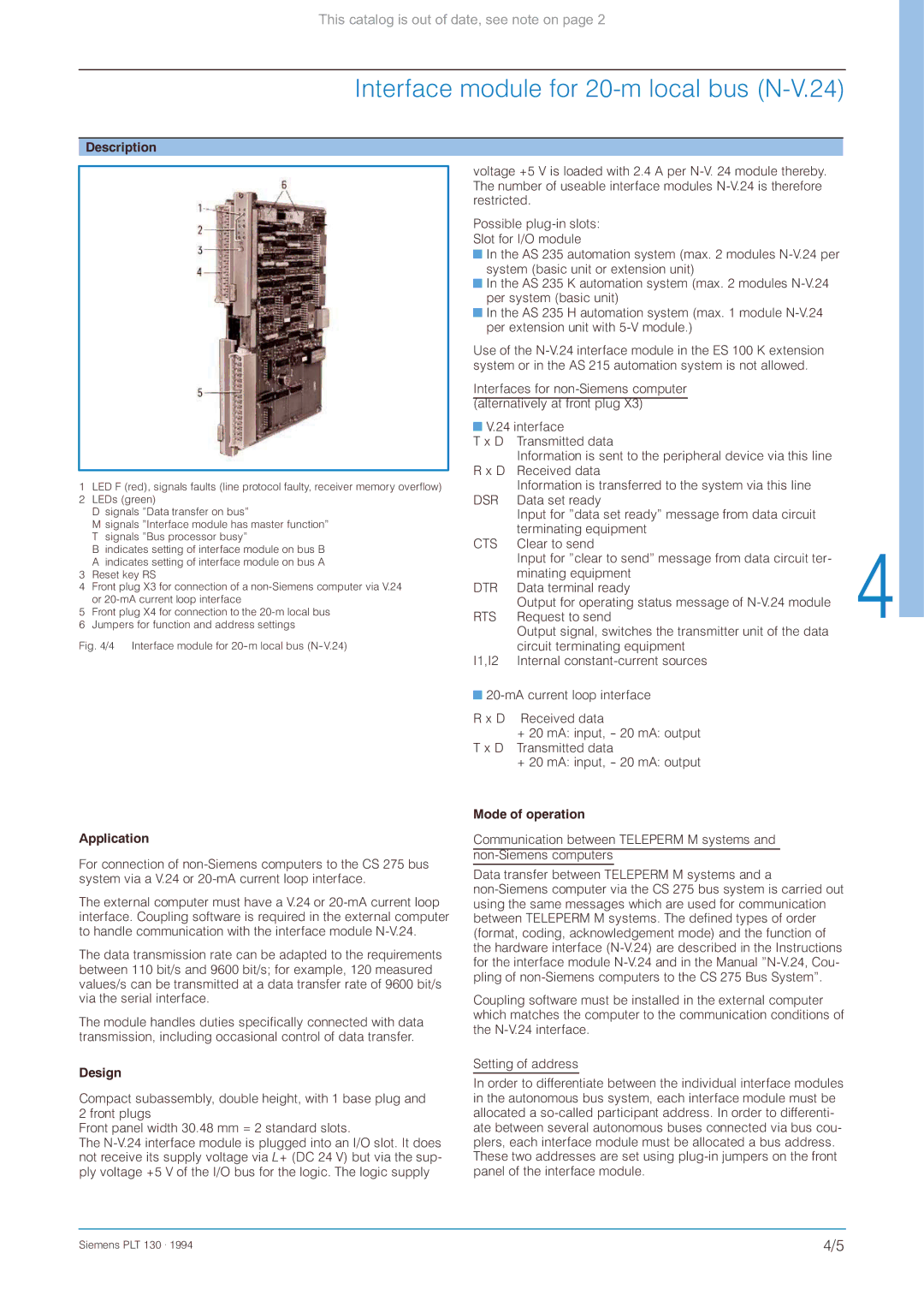
Description
1LED F (red), signals faults (line protocol faulty, receiver memory overflow)
2 LEDs (green)
D signals ”Data transfer on bus”
M signals ”Interface module has master function” T signals ”Bus processor busy”
B indicates setting of interface module on bus B A indicates setting of interface module on bus A
3 Reset key RS
4 Front plug X3 for connection of a
5 Front plug X4 for connection to the
Fig. 4/4 Interface module for 20-m local bus (N-V.24)
voltage +5 V is loaded with 2.4 A per
Possible
![]() In the AS 235 automation system (max. 2 modules
In the AS 235 automation system (max. 2 modules
![]() In the AS 235 K automation system (max. 2 modules
In the AS 235 K automation system (max. 2 modules
![]() In the AS 235 H automation system (max. 1 module
In the AS 235 H automation system (max. 1 module
Use of the
Interfaces for
(alternatively at front plug X3)
![]() V.24 interface
V.24 interface
T x D | Transmitted data |
| Information is sent to the peripheral device via this line |
R x D | Received data |
| Information is transferred to the system via this line |
DSR | Data set ready |
| Input for ”data set ready” message from data circuit |
| terminating equipment |
CTS | Clear to send |
| Input for ”clear to send” message from data circuit ter- |
| minating equipment |
DTR | Data terminal ready |
| Output for operating status message of |
RTS | Request to send |
| Output signal, switches the transmitter unit of the data |
| circuit terminating equipment |
I1,I2 | Internal |
![]()
R x D Received data
+20 mA: input,
+20 mA: input,
Application
For connection of
The external computer must have a V.24 or
The data transmission rate can be adapted to the requirements between 110 bit/s and 9600 bit/s; for example, 120 measured values/s can be transmitted at a data transfer rate of 9600 bit/s via the serial interface.
The module handles duties specifically connected with data transmission, including occasional control of data transfer.
Design
Compact subassembly, double height, with 1 base plug and 2 front plugs
Front panel width 30.48 mm = 2 standard slots.
The
Mode of operation
Communication between TELEPERM M systems and
Data transfer between TELEPERM M systems and a
Coupling software must be installed in the external computer which matches the computer to the communication conditions of the
Setting of address
In order to differentiate between the individual interface modules in the autonomous bus system, each interface module must be allocated a
Siemens PLT 130 . 1994 | 4/5 |