This catalog is out of date, see note on page 2
Mode of operation
Transfer control, data protection and transfer
Transfer control
Sequential data transmission systems require a transfer control unit for organization of the data traffic on the line. This unit orga- nizes and coordinates the data traffic so that only one sub- scriber transmits data on the bus at a time. This transfer control function is decentralized in the CS 275 bus system. The avail- ability of the data transmission system is therefore mainly deter- mined by the line length.
Data transfer control in the CS 275 bus system operates accord- ing to the token principle, i. e. each participant (local bus inter- face module) accepts the transfer control function (master func- tion) from time to time.
In a system with n participants, there is only one participant in the master condition at any one time, all other
The ”bus protocol” also specifies how a participant becomes master and how this status is transferred within the system. The protocol complementary methods for the assignment of the master function to a participant are:
![]()
![]()
![]()
Data protection
Data protection is achieved in the CS 275 bus system by gener- ating line and column parities and is referred to as block parity.
The following errors are detected by the data protection:
![]()
![]() Hamming distance d = 4
Hamming distance d = 4
![]() Odd bit errors,
Odd bit errors,
![]() Error bursts < 11 bit long
Error bursts < 11 bit long
![]() Error pattern (with exception of rectangular format).
Error pattern (with exception of rectangular format).
The bit error rate of p
Data transfer
Blocks in the TELEPERM M system components are available for a cyclic and a sporadic (acyclic) data transfer via the bus system:
Dedicated transmitter and receiver blocks handle all functions associated with data transfer. Thus, the data transfer can be established easily by configuring, just as the automation func- tions.
The user need only carry out the following to produce commu- nication:
This presents the following advantages:
![]() Easy configuring of communication (only the transmitter and receiver blocks must be configured, not the interface modules for
Easy configuring of communication (only the transmitter and receiver blocks must be configured, not the interface modules for
![]() Messages to several subscribers are simply transmitted on the bus (several receiver blocks can access one transmitter block)
Messages to several subscribers are simply transmitted on the bus (several receiver blocks can access one transmitter block)
![]() Symbolic addressing (block name and number)
Symbolic addressing (block name and number)
![]() Complete documentation of all connections by
Complete documentation of all connections by
![]() The communication procedure can be configured in a still simpler manner in
The communication procedure can be configured in a still simpler manner in
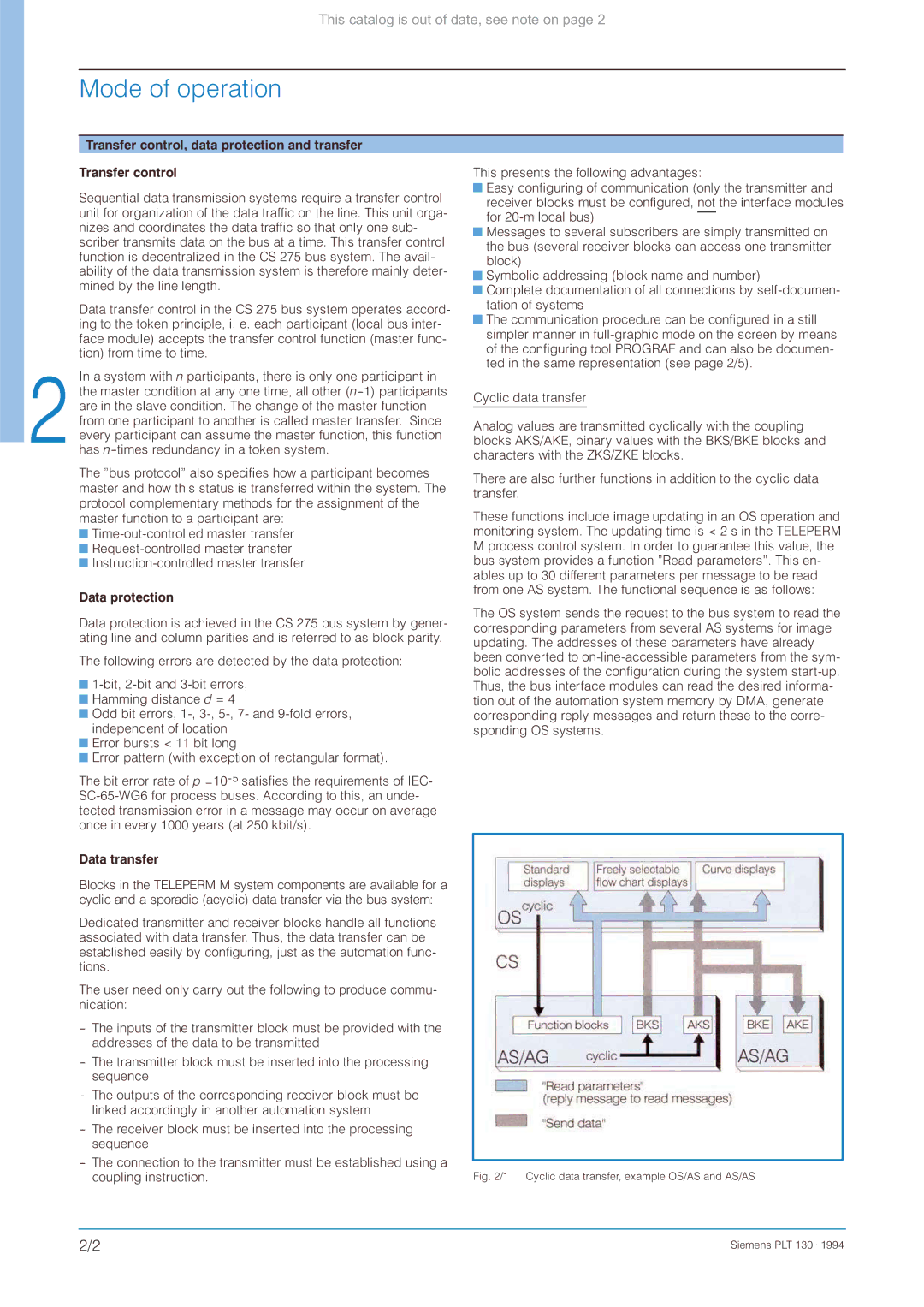
Cyclic data transfer
Analog values are transmitted cyclically with the coupling blocks AKS/AKE, binary values with the BKS/BKE blocks and characters with the ZKS/ZKE blocks.
There are also further functions in addition to the cyclic data transfer.
These functions include image updating in an OS operation and monitoring system. The updating time is < 2 s in the TELEPERM M process control system. In order to guarantee this value, the bus system provides a function ”Read parameters”. This en- ables up to 30 different parameters per message to be read from one AS system. The functional sequence is as follows:
The OS system sends the request to the bus system to read the corresponding parameters from several AS systems for image updating. The addresses of these parameters have already been converted to
Fig. 2/1 Cyclic data transfer, example OS/AS and AS/AS
2/2 | Siemens PLT 130 . 1994 |