This catalog is out of date, see note on page 2
Bus coupler
Technical data and ordering data
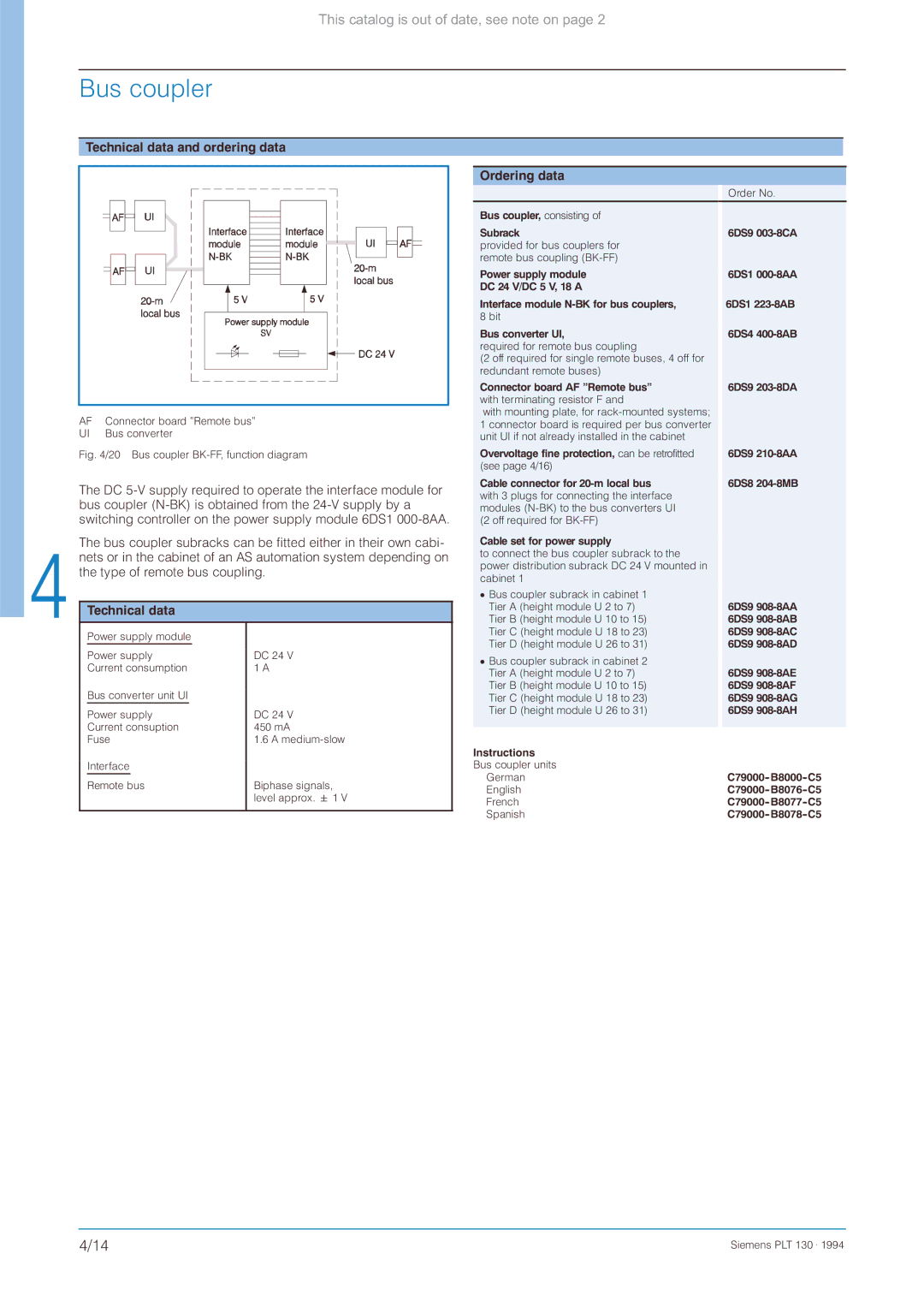
AF | Connector board ”Remote bus” |
UI | Bus converter |
Fig. 4/20 Bus coupler BK-FF, function diagram
The DC
The bus coupler subracks can be fitted either in their own cabi- nets or in the cabinet of an AS automation system depending on the type of remote bus coupling.
Technical data
Power supply module |
| |||
|
|
|
|
|
Power supply | DC 24 V | |||
Current consumption | 1 A | |||
Bus converter unit UI |
| |||
|
|
|
|
|
Power supply | DC 24 V | |||
Current consuption | 450 mA | |||
Fuse | 1.6 A | |||
Interface |
| |||
|
|
|
|
|
Remote bus | Biphase signals, | |||
|
|
|
| level approx. 1 V |
|
|
|
|
|
Ordering data
|
| Order No. |
Bus coupler, consisting of |
|
|
Subrack |
| 6DS9 |
provided for bus couplers for |
|
|
remote bus coupling |
|
|
Power supply module |
| 6DS1 |
DC 24 V/DC 5 V, 18 A |
|
|
Interface module |
| 6DS1 |
8 bit |
|
|
Bus converter UI, |
| 6DS4 |
required for remote bus coupling |
|
|
(2 off required for single remote buses, 4 off for |
|
|
redundant remote buses) |
|
|
Connector board AF ”Remote bus” |
| 6DS9 |
with terminating resistor F and |
|
|
with mounting plate, for |
|
|
1 connector board is required per bus converter |
|
|
unit UI if not already installed in the cabinet |
|
|
Overvoltage fine protection, can be retrofitted |
| 6DS9 |
(see page 4/16) |
|
|
Cable connector for |
| 6DS8 |
with 3 plugs for connecting the interface |
|
|
modules |
|
|
(2 off required for |
|
|
Cable set for power supply |
|
|
to connect the bus coupler subrack to the |
|
|
power distribution subrack DC 24 V mounted in |
|
|
cabinet 1 |
|
|
¯ Bus coupler subrack in cabinet 1 |
| 6DS9 |
Tier A (height module U 2 to 7) |
| |
Tier B (height module U 10 to 15) |
| 6DS9 |
Tier C (height module U 18 to 23) |
| 6DS9 |
Tier D (height module U 26 to 31) |
| 6DS9 |
¯ Bus coupler subrack in cabinet 2 |
|
|
Tier A (height module U 2 to 7) |
| 6DS9 |
Tier B (height module U 10 to 15) |
| 6DS9 |
Tier C (height module U 18 to 23) |
| 6DS9 |
Tier D (height module U 26 to 31) |
| 6DS9 |
|
|
|
Instructions |
|
|
Bus coupler units |
|
|
German |
| |
English |
| |
French |
| |
Spanish |
|
4/14 | Siemens PLT 130 . 1994 |