|
| Automation and Drives - SCE |
Assignment List: |
|
|
Symbol: | Address: | Comment |
AI_w | PEW 128 | Analog input setpoint generator 0…10V |
AI_X | PEW 130 | Analog input sensor actual value 0…10V |
AO_Y | PAW 128 | Analog output manipulated variable 0 … 10V |
M_w | MD40 | Internal setpoint (floating point number normalized) |
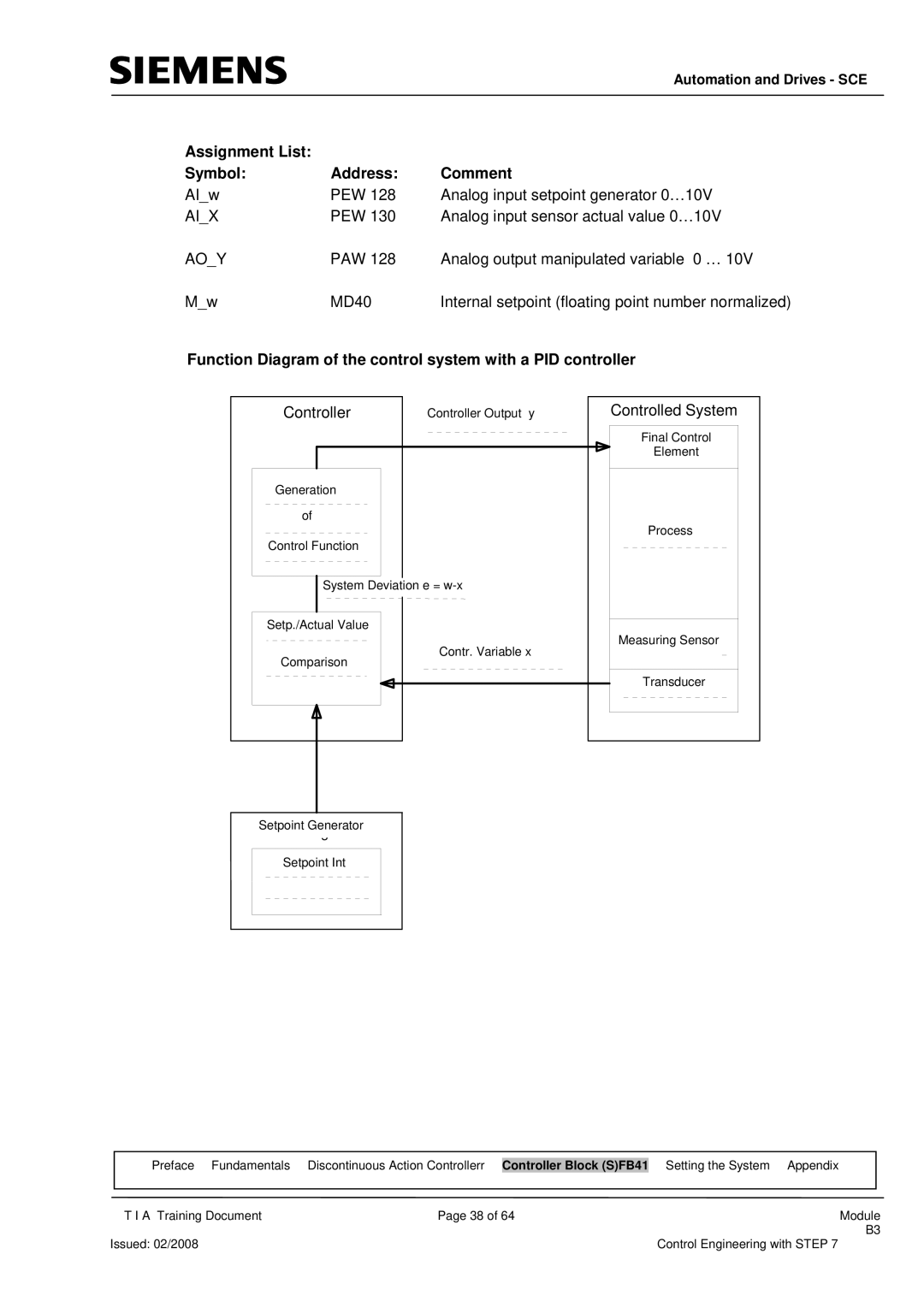
Function Diagram of the control system with a PID controller
| Controller |
|
|
|
| ControlledRegelstreckeSystem | ||
|
|
| Controller Output y | |||||
| Regler |
|
| Stellgröße y |
|
|
|
|
|
|
| ||||||
|
|
|
|
|
|
| Final Control |
|
|
|
|
|
|
|
|
| |
|
|
|
|
|
|
| Stellglied |
|
|
|
|
|
|
|
| Element |
|
|
|
|
|
|
|
|
| |
Generation |
|
|
|
|
|
|
| |
| Bildung |
|
|
|
|
|
|
|
|
|
|
|
|
|
|
|
|
| of |
|
|
|
|
|
|
|
| der |
|
|
|
|
| Process | |
|
|
|
|
|
|
| ||
|
|
|
|
|
|
| Prozess | |
ControlRegelfunktionFunction
Setp./Actual Value
ComparisonVergleichContrRegelgröße. Variablexx
Setpoint Generator
Sollwertgeber
Setpoint Int
Sollwert Int
MeasurinMessgeberSensor
Transducer
Messumformer
|
|
|
|
|
|
|
| Preface Fundamentals | Discontinuous Action Controllerr | Controller Block (S)FB41 |
| Setting the System Appendix |
|
|
|
|
|
|
|
|
| T I A Training Document | Page 38 of 64 | Module | |||
|
|
|
|
| B3 | |
Issued: 02/2008 |
|
|
| Control Engineering with STEP 7 | ||