Automation and Drives - SCE
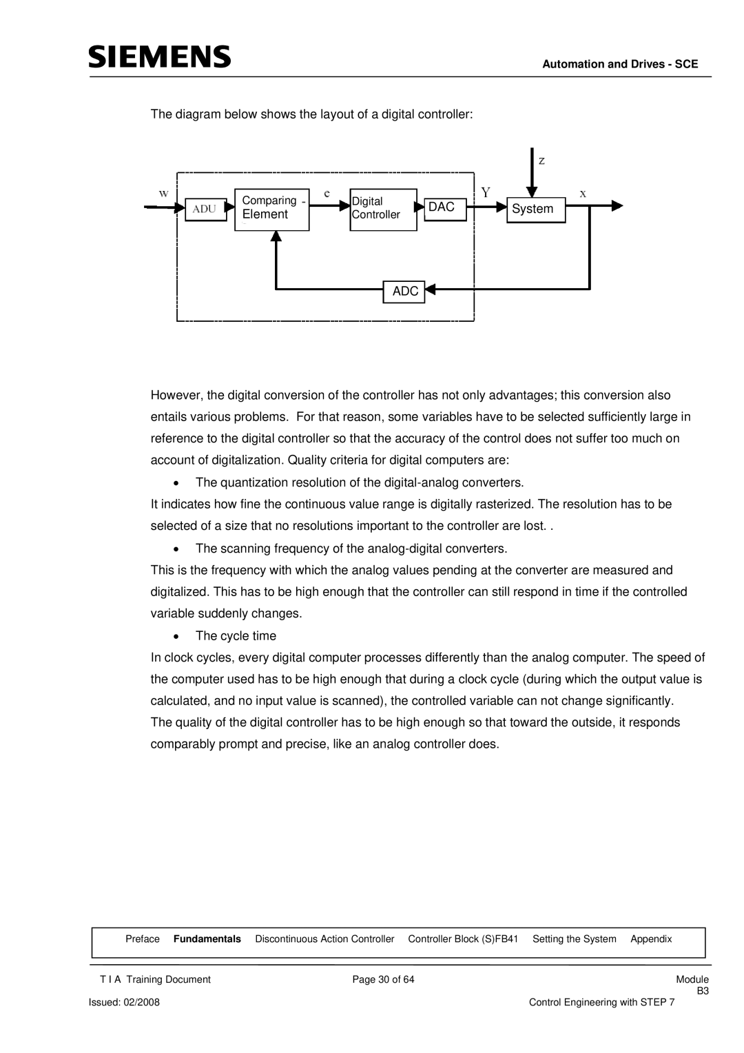
The diagram below shows the layout of a digital controller:
Comparing |
| Digital |
|
|
|
|
|
| DAC |
|
| ||
|
| System | ||||
Element |
| Controller |
|
| ||
|
|
|
|
| ||
|
|
|
| |||
|
|
|
|
|
|
|
ADC
However, the digital conversion of the controller has not only advantages; this conversion also entails various problems. For that reason, some variables have to be selected sufficiently large in reference to the digital controller so that the accuracy of the control does not suffer too much on account of digitalization. Quality criteria for digital computers are:
•The quantization resolution of the
It indicates how fine the continuous value range is digitally rasterized. The resolution has to be selected of a size that no resolutions important to the controller are lost. .
•The scanning frequency of the
This is the frequency with which the analog values pending at the converter are measured and digitalized. This has to be high enough that the controller can still respond in time if the controlled variable suddenly changes.
•The cycle time
In clock cycles, every digital computer processes differently than the analog computer. The speed of the computer used has to be high enough that during a clock cycle (during which the output value is calculated, and no input value is scanned), the controlled variable can not change significantly.
The quality of the digital controller has to be high enough so that toward the outside, it responds comparably prompt and precise, like an analog controller does.
| Preface | Fundamentals Discontinuous Action Controller Controller Block (S)FB41 Setting the System Appendix |
| ||
|
|
|
|
| |
| T I A Training Document | Page 30 of 64 | Module | ||
|
|
|
| B3 | |
Issued: 02/2008 |
|
| Control Engineering with STEP 7 | ||