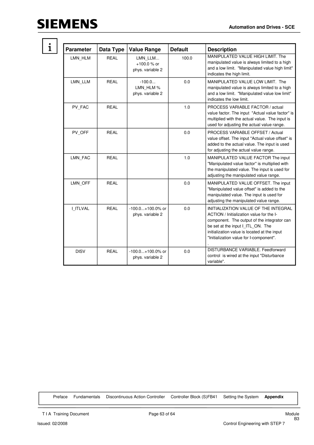
Parameter | Data Type | Value Range | Default |
LMN_HLM | REAL | LMN_LLM... | 100.0 |
|
| +100.0 % or |
|
|
| phys. variable 2 |
|
|
|
|
|
LMN_LLM | REAL | 0.0 | |
|
| LMN_HLM % |
|
|
| phys. variable 2 |
|
|
|
|
|
PV_FAC | REAL |
| 1.0 |
PV_OFF | REAL | 0.0 |
LMN_FAC | REAL | 1.0 |
LMN_OFF | REAL | 0.0 |
I_ITLVAL | REAL | 0.0 | |
|
| phys. variable 2 |
|
DISV | REAL | 0.0 | |
|
| phys. variable 2 |
|
Automation and Drives - SCE
Description
MANIPULATED VALUE HIGH LIMIT. The manipulated value is always limited to a high and a low limit. "Manipulated value high limit" indicates the high limit.
MANIPULATED VALUE LOW LIMIT. The manipulated value is always limited to a high and a low limit. "Manipulated value low limit" indicates the low limit.
PROCESS VARIABLE FACTOR / actual value factor. The input "Actual value factor" is multiplied with the actual value. The input is used for adjusting the actual value range.
PROCESS VARIABLE OFFSET / Actual value offset. The input "Actual value offset" is added to the actual value. The input is used for adjusting the actual value range.
MANIPULATED VALUE FACTOR The input "Manipulated value factor" is multiplied with the manipulated value. The input is used for adjusting the manipulated value range.
MANIPULATED VALUE OFFSET. The input "Manipulated value offset" is added to the manipulated value. The input is used for adjusting the manipulated value range.
INITIALIZATION VALUE OF THE INTEGRAL ACTION / Initialization value for the I- component. The output of the integrator can be set at the input I_ITL_ON. The initialization value is located at the input "Initialization value for
.
DISTURBANCE VARIABLE. Feedforward control is wired at the input "Disturbance variable".
| Preface Fundamentals | Discontinuous Action Controller Controller Block (S)FB41 | Setting the System Appendix |
|
|
|
|
|
|
| T I A Training Document | Page 63 of 64 | Module | |
|
|
| B3 | |
Issued: 02/2008 |
| Control Engineering with STEP 7 | ||