Simatic
Safety Guidelines
Required Basic Knowledge
Purpose of the Manual
Scope of this Manual
Approvals
Recycling and Disposal
Navigating
Further Support
Training Centers
Technical Support
Service & Support on the Internet
Preface
Contents
Contents
Assembling and Installing Systems
Maintenance
Figures
Routing Equipotential Bonding Conductor and Signal Line
Tables
Overview of the S7-400
Features of the S7-400
Components Function Illustration
S7-400 components
Location of the order number and product version
Example of a rating plate
Section Description
Chapter Overview
S7-400 Installation
Introduction
Central Rack CR and Expansion Rack ER
Connecting with a 5 V Supply
Connecting the CR and ERs
Overview of the Connections
Local Connection Remote Connection
Ways of Connecting Central and Expansion Racks
Type of Connection Maximum Total Cable Length
Rules for Connection
Rack No. Available Application Characteristics Slots Buses
Installing the Central Rack CR and Expansion Rack ER
Function of the Racks
Racks in the S7-400 System
Bus
Electrical Supply
Communication Bus C Bus
Rack with I/O Bus and Communication Bus
Properties
Segmented CR
Subdivided CR
Characteristics
Important Notes on Installation
Mounting and Grounding the Racks
Retaining Distances Between Devices
Dimensions of the Racks
Mounting the Rack
Connecting the Rack to the Chassis Ground
Mounting Screws
Screw Type Explanation
Mounting Additional Racks
840 mm Cable duct/fan subassembly
Reference Point
Ungrounded configuration Grounded configuration
Connection to the Reference Point
M4 x
Methods of Ventilation
Methods of Ventilation
Wall
Changing the Ventilation
Filter Mat Optional
Shipping state
Procedure
Installing the Fan Subassembly
Monitoring the Fan Subassembly
Installing the Cable Duct
Choosing and Setting up Cabinets with the S7-400
Why Cabinets are Required
Types and Dimensions of Cabinets
Open Cabinets Closed Cabinets
Removable Power Dissipation from Cabinets Example
Cabinet dimensions
Example of selecting the cabinet type
Type of Cabinet Max. Permissible Ambient
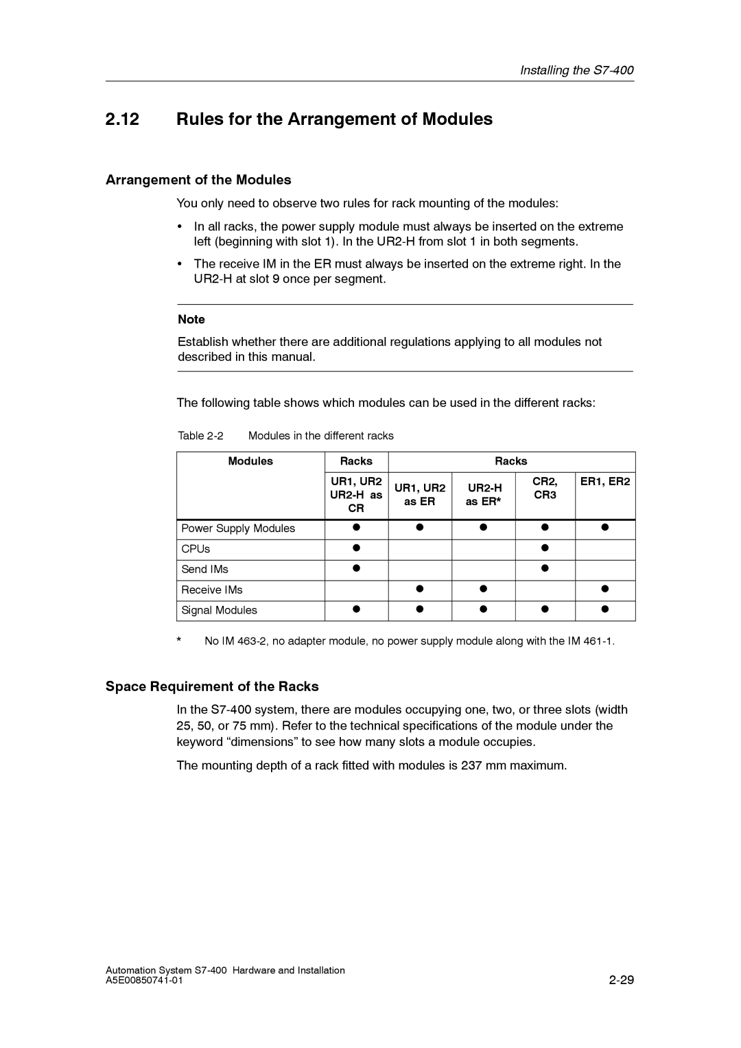
Arrangement of the Modules
Rules for the Arrangement of Modules
Space Requirement of the Racks
Modules
Installing Modules in a Rack
Installation Sequence
Tool
Removing the Cover
Screwing the Modules in Place
Attaching the Modules
Marking the Modules with Slot Labels
Slot Number
Fitting Slot Labels
Methods of Expansion and Networking
Distributed I/Os
Networking
Accessories
Accessories
Installing the S7-400
Addressing the S7-400
Addresses
Geographical and Logical Addresses
Geographical Addresses
Logical Addresses
Conditions for Default Addressing
Default Addressing
How to Determine the Default Address of a Module
Default Addresses of Digital Modules
Example
Default Addresses of Analog Modules
Channel on a Digital Module
How to Determine the Default Address of a Channel
Channel on an Analog Module
Addressing the S7-400
Wiring the S7-400
Power Supply Modules and Load Current Power Supplies
Supplying Power to Modules
Estimating the Power Requirement
Choosing the Power Supply Module
Calculation Example
Module Quantity +5 VDC Max. Current Consumption
Choosing the Load Current Power Supply
Choosing the Load Current Power Supply
Load Current Power Supplies
Determining the Load Current
Definition of a Grounded Supply TN-S Network
Assembling an S7-400 with Process I/Os
Components and Protective Measures
Rule Grounding the Load Current Circuits
CPU
S7-400 in the Overall Installation
Application
Assembling an S7-400 with Grounded Reference Potential M
Discharge of Interference Currents
Terminal Connection Model
An S7-400 Configured with Ungrounded Reference Potential
Power Supply Units
Filtering the 24 VDC Supply
Insulation Monitoring
Example of Ungrounded Operation
Assembling an S7-400 with Isolated Modules
Definition
Isolated Modules and Grounding Concept
Configuration with Isolated Modules
Parallel Wiring of Digital S7-400 Outputs
Ground Connections
Grounding
Protective Ground
Device Grounding Method
Mode Connection of Load Voltage
Connecting the Load Voltage Ground
Interference-Free Configuration for Local Connections
Interference-Free Configuration for Remote Connections
Use only Approved Components
Special Cases
Lines and Tools
Wiring Rules
Wiring the Power Supply Module
Power Supply Connector
Disconnecting the Power Supply Connector
Wiring the Power Supply Connector
AC DC L1 L+
11 Plugging the power supply connector
Plugging In the Power Supply Connector
Three Types of Front Connector
Wiring the Signal Modules
12 Preparing to wire the front connector
Preparing to Wire the Front Connector
13 Wiring a Front Connector with Crimp Terminals
Wiring the Front Connector, Crimping
14 Wiring a Front Connector with Screw-Type Terminals
Wiring the Front Connector, Screw Terminals
15 Wiring a Front Connector with Spring-Type Terminals
Wiring the Front Connector, Spring-Type Terminals
16 Principle of the spring contact
Principle of the spring loaded terminal
Cable Ties as Strain Relief
Fitting the Strain Relief
Labels and Terminal Diagram
Labeling a Front Connector
Labels
19 shows details for fitting a label in the front connector
Order Number Description
How to Label S7-400 Modules
Front Connector Coding on the Signal Modules
Fitting the Front Connector
Plugging In the Front Connector
Principle of a Coding Key
20 Attaching the Front Connector
21 shows how to screw on the front connector
Interconnecting the Interface Modules
Interconnecting the CR and ERs
23 Connection Between a Send IM and Two Receive IMs
Setting the Fan Subassembly to the Line Voltage
Wiring the Fan Subassembly
Fuse
Routing Fiber-Optic Cables
Cable routing in cable ducts or fan subassemblies
Networking
Same Configuration
Configuring a Network
Configuring Communication
Subnets
Station = Node
Fundamentals
Segment
Baud Rate
Node Device Default MPI Address Default Highest MPI
Default MPI Addresses
Number of Nodes
MPI/PROFIBUS-DP Addresses
Rules for MPI Addresses
PG / OP -- Module communication without MPI
Maximum Number of Connections via MPI
PG Access
Rules
Rules for Configuring a Network
Recommendation for MPI Addresses
Data Packets in the MPI Network
Recommendation for PROFIBUS-DP Addresses
Components
Terminating Resistor on the RS 485 Repeater
Terminating Resistor on the Bus Connector
Example Terminating Resistor in the MPI Network
Example of an MPI Network
Example of a PROFIBUS-DP Network
PROFIBUS-DP
Example Using a CPU
Programming device access beyond network limits
Programming Device Access Beyond Network Limits Routing
Segment in the MPI Network
Cable Lengths
Segment in the PROFIBUS-DP Network
Longer Cable Lengths
Lengths of Spur Lines
10 Configuration of an MPI network
PROFIBUS-DP Bus Cables
Characteristics of the PROFIBUS-DP Bus Cable
PROFIBUS-DP Bus Cables
Rules for Laying Cables
Bus Connectors
Purpose of the Bus Connector
Appearance 6ES7972-0B.20
Connecting Bus Cables to Bus Connectors 6ES7972-0B.20
Connecting the Bus Connector
Removing the Bus Connector
RS 485 Repeater / Diagnostics Repeater
PROFIBUS-DP Network with Fiber-Optic Cables
Electrical/Optical Conversion
Benefits and Areas of Application
Transmission Rate
Optical PROFIBUS-DP Network in Partyline Topology
Profibus Optical Bus Terminal OBT
Features of the Fiber-Optic Cables
Cable grip
Prerequisite
Order Numbers
Simatic NET Profibus plastic fiber-optic, standard cable
Simatic NET Profibus PCF fiber-optic, standard cable
Structure
Accessories Order Number
Mixed Use of Plastic Fiber-Optic and PCF Fiber-Optic Cable
Cable Lengths
Laying PCF Fiber-Optic Cable
Laying Plastic Fiber-Optic Cable
Rules for Laying Cable
Installing the Connector Adapter
Networking
Commissioning
Recommended Procedure for First Startup
Recommended Procedure
How to Proceed in the Case of an Error
Checks Prior to Switching On for the First Time
Checks Prior to Switching On for the First Time
Mounting and Wiring Modules
Grounding and Chassis Ground Concept
Module Settings
Power Supply Module
Line Voltage
Connecting a Programming Device PG to an S7-400
Connecting a Programming Device PG to an S7-400
If You Then
Switching On an S7-400 for the First Time
Switching On an S7-400 for the First Time
Switching On an H System for the First Time
Communication between Programming Device and CPU
How to Carry Out a Memory Reset
Resetting the CPU with the Mode Selector Switch
When Should a CPU be Reset?
How to Perform a Memory Reset
Resetting the CPU with the Mode Selector Switch
What Happens in the CPU During a Memory Reset
What Remains Following the Memory Reset
Special Case MPI Parameters
Restart warm start
Cold, Warm, and Hot Restarts with the Mode Selector Switch
Hot restart
Control sequence for restart warm restart / hot restart
Inserting a Memory Card
Memory Card as Load Memory
What Type of Memory Card Should You Use?
Inserting a Memory Card
Inserting a Backup Battery Option
Backup
Inserting a Backup Battery
Commissioning
Commissioning
Reducing the Passivation Layer
Removing a Backup Battery
Requirements
Starting Up a PROFIBUS-DP Subnet
Starting Up
Behavior of the CPU During Startup
Available Interface Modules
Installing Interface Modules
Covering Unused Submodule Slots
Commissioning
Maintenance
Replacing the Backup Battery
Replacing the Backup Battery
Rules for the Care of Backup Batteries
Using Backup Batteries
Installing a New Module
Replacing a Power Supply Module
Slot Numbering
How the S7-400 Behaves after Exchanging Modules
Replacing CPUs
Saving the Data
Removing the Module
Installing a New Module
Replacing Digital or Analog Modules
Installing a Module
Exchanging the Front Connector
Removing the Front Connector Coding Key
Modules with Fuses
Changing the Fuses in the Digital Modules
Check the Plant
Changing the Fuses
How the S7-400 Behaves after Replacing the Fuse
Replacing Interface Modules
Hot--swapping Modules
Removing Modules / Exchanging Cables
Installing a New Module
Replacing the Fuse of the Fan Subassembly
Fuse Type
Replacing the Fuse
Removing the Fans
Replacing Fans in the Fan Subassembly During Operation
Maintenance
Replacing the Filter Frame
Maintenance
Exchanging the Mother Board
Installing Interface Submodules
Replacing Interface Submodules
Available Interface Submodules
Inserting an Interface Submodule in a CPU
Assembling and Installing Systems
General Basic Rules
General Rules and Regulations for Operating the S7-400
Specific Application
Emergency OFF Devices
VDC Supply
120/230 VAC Supply
Protection Against External Electrical Effects
With You Must Ensure
Protection against By Means
Protection Against Other Electrical Effects
Principles of System Installation for EMC
Definition EMC
Possible Effects of Interference
Capacitive Coupling
Coupling Mechanisms
Inductive Coupling
Radiated Interference
Rule 1 Large Area Grounding
Five Basic Rules for Ensuring Electromagnetic Compatibility
Rule 2 Correct Cable Routing
Rule 3 Secure Cable Shields
Rule 4 Special EMC Measures
Rule 5 Standard Reference Potential
See also
Grounding of Inactive Metal Parts During Installation
Installation of Programmable Controllers for EMC
Ensure the following when chassis grounding
Inactive Metal Parts
Example 1 Cabinet Configuration for EMC
Examples of EMC-Compatible Assembly
Example 2 EMC--compliant Wall Mounting
Key for example
Figure A-3 shows an example of wall mounting for EMC
Ensure the following for frame and wall mounting
Purpose of the Shielding
Shielding Cables
Principle of Operation
Suitable Cables
Figure A-4 Mounting Cable Shields
Handling the Shields
Equipotential Bonding
Potential Differences
Equipotential Bonding Conductor
Assembling and Installing Systems
Cabling Inside Buildings
How to Read the Table
Connect Cables for Run
Inside cabinets
Ethernet
Rules for EMC
Cabling Outside Buildings
Rules for Lightning Protection Outside Buildings
Overvoltage Protection Devices
Overview
Lightning Protection and Overvoltage Protection
Surges
Effects of a Lightning Strike
Figure A-6 Lightning Protection Zones of a Building
Diagram of the Lightning Protection Zones
Additional Measures
Ser Cables for Equip transition point 0 With
Order No
Dehn + Söhne
Lightning Protection Element for the 24 VDC Supply
Lightning Protection Element for Signal Modules
Ser Cables for Equip transition point 1 2 with Order No
Low-Voltage Protection Elements for 1
Ser Cables for Equip transition point Order No With
Low-Voltage Protection Elements for 2
Sample Circuit
Lightning-protection 0, field side zone
Lightning-protection zone
Ser. No Components Description From fi Gure A-7
Components in figure A-7
Inductive Surge Voltage
Integrated Surge Arrester
Additional Overvoltage Protection
Suppression for DC-Operated Coils
Suppression with Diodes / Zener Diodes
Suppression with AC-Operated Coils
Safety of Electronic Control Equipment
Intoduction Reliability
Risks
Important Information
Interference-Free Connection of Monitors
Operation under Low-Interference Conditions
Operation under Industrial Conditions
Shielding and Grounding under Industrial Conditions
Isolated
Section You will find
What is ESD?
Charging
Electrostatic Charging of Persons
Avoid Direct Contact
Ensure Sufficient Grounding
Address
Backup Battery
Analog Module
Bit Memory M
Configuring
Configuration
Central module
Chassis Ground
Counters
Default Setting
Cycle time
Cyclic Interrupt
Diagnostic Interrupt
Diagnostic Buffer
DP Master
DP Slave
Error Display
Error Response
Function
Function Block FB
Functional Grounding
Function Module FM
Global Data Communication
Instance Data Block
Hardware Interrupt
Interface, Multipoint
Interrupt, Cyclic
Local Data
Load Memory
Logic Block
Manufacturer--specific interrupt
Nesting Depth
MPI Address
Network
Node Number
Operating State
OB Priority
Operating System of the CPU
Organization Block OB
Priority classes
Parameters, Static
Process Image
Programming Device PG
Reference Ground
Run-Time Error
Reference Potential
Retentive Data
Slave
Signal Module
Status interrupt
Substitute Value
Time-Delay Interrupt
System Diagnostics
System Function SFC
System Function Block SFB
Toggle switch
Timer T
Update interrupt
Total Current
Warm Restart
Varistor
Watchdog interrupt
Work Memory
Index
Index
Index-3
Index-4