SpectraLink Corporation | Link WTS Installation and Operation |
2.2The Front Panel of the Link 150 M3 MCU
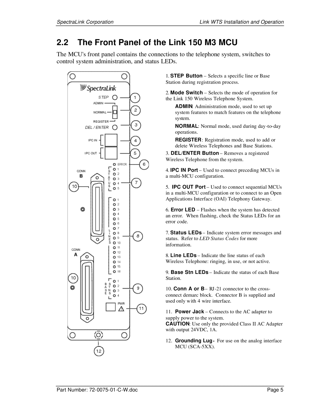
The MCU's front panel contains the connections to the telephone system, switches to control system administration, and status LEDs.
1.STEP Button – Selects a specific line or Base Station during registration process.
2.Mode Switch – Selects the mode of operation for the Link 150 Wireless Telephone System.
ADMIN: Administration mode, used to set up system features to match features on the telephone system.
NORMAL: Normal mode, used during day
REGISTER: Registration mode, used to add or delete Wireless Telephones and Base Stations.
3.DEL/ENTER Button – Removes a registered Wireless Telephone from the system.
4.IPC IN Port – Used to connect preceding MCUs in a
5.IPC OUT Port – Used to connect sequential MCUs in a
6.Error LED – Flashes when the system has detected an error. When flashing, check the Status LEDs for an error code.
7.Status LEDs – Indicate system error messages and status. Refer to LED Status Codes for more information.
8.Line LEDs – Indicate the line status of each Wireless Telephone: ringing, in use, or not active.
9.Base Stn LEDs – Indicate the status of each Base Station.
10.Conn A or B– RJ
11.Power Jack – Connects to the AC adapter to supply power to the system.
CAUTION: Use only the provided Class II AC Adapter with output 24VDC, 1A.
12.Grounding Lug- For use on the analog interface MCU
Part Number: | Page 5 |