SpectraLink Corporation | Link WTS Installation and Operation |
4.2Pull Cable
Pull the cable from the MCU location (usually in the telephone equipment room) to the Base Station locations designated on the floor plans.
If the cabling exits the building, consult the telephone system manual, the NEC, and local codes for instructions on providing lightning and other over- current protection.
When cabling an external Base Station or a Base Station with wiring that exits the building, protect all Base Station wiring with the Quick Clip Fuse (Illinois Tool Works, Linx Division,
Run all cable before attaching the
Remove bridge taps, multiples, or "Y" connections to the Base Station wires;
!these will cause data transmission errors.
The area above some suspended ceilings is used as an environmental air plenum. The National Electric Code requires that wire installed in plenums be rated for plenum installation.
4.3Terminate Cable at Base Station Locations
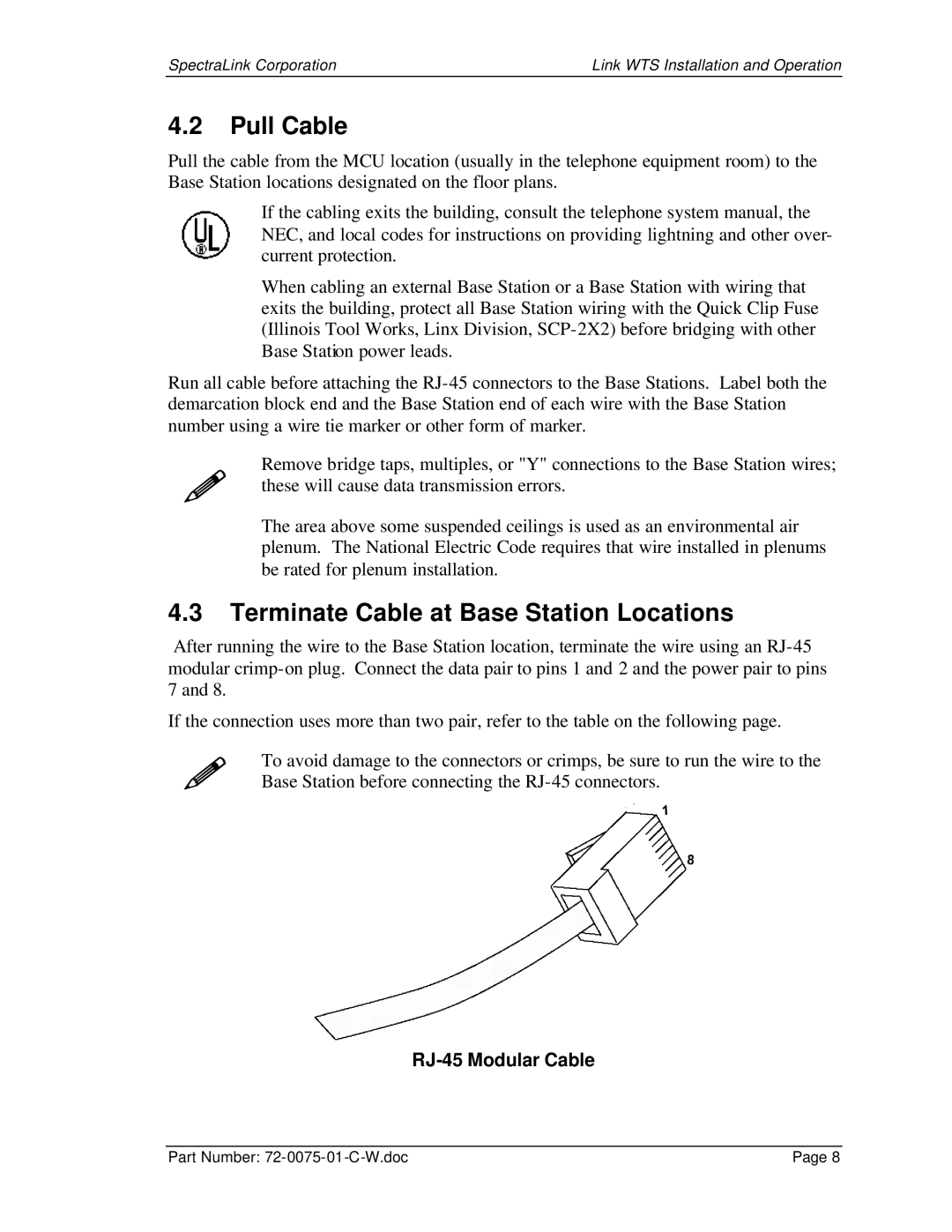
After running the wire to the Base Station location, terminate the wire using an
If the connection uses more than two pair, refer to the table on the following page.
! To avoid damage to the connectors or crimps, be sure to run the wire to the Base Station before connecting the
RJ-45 Modular Cable
Part Number: | Page 8 |