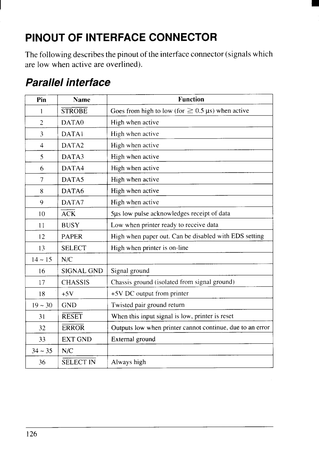
NX-2415II specifications
The Star Micronics NX-2415II is a versatile and advanced printer designed primarily for point-of-sale (POS) applications. Known for its reliability and efficient performance, it serves as an excellent solution for various retail and hospitality environments. This printer stands out due to its compact design, making it easy to fit into tight spaces while providing superior functionality.One of the key features of the NX-2415II is its ability to handle multiple printing tasks. With high-speed printing capabilities, it can produce receipts, tickets, and labels at an impressive rate, minimizing customer wait times. Its print speed reaches up to 250mm per second, ensuring that businesses can operate efficiently during peak hours.
The NX-2415II incorporates advanced connectivity options, including USB, Ethernet, and Bluetooth, providing users with the flexibility to choose the connection method that best suits their setup. This multifunctional connectivity enables seamless integration with various POS systems and mobile devices, enhancing overall operational efficiency.
The printer uses high-quality thermal printing technology, which eliminates the need for messy ink and toner. This means lower maintenance costs and reduced hassle for users. Additionally, the NX-2415II supports various paper widths and types, allowing businesses to customize their printed materials according to their needs.
Another notable characteristic of the NX-2415II is its durability. Built with robust materials, this printer can withstand the demands of busy commercial settings, making it an ideal choice for environments that require consistent and reliable performance. Its design also includes features that prevent paper jams and enhance overall operational longevity.
For enhanced user experience, the NX-2415II comes equipped with an easy-to-read LCD display and simple control buttons. This user-friendly interface ensures that even new users can quickly navigate the printer's functions without extensive training. Furthermore, the printer’s energy-efficient design helps reduce overall power consumption, contributing to environmental sustainability.
In summary, the Star Micronics NX-2415II is a powerful and efficient printing solution for modern businesses. Its high-speed performance, versatile connectivity options, and durable construction make it an essential tool for retail and hospitality sectors looking to improve service quality and operational efficiency. Whether printing receipts, tickets, or labels, the NX-2415II meets diverse printing needs with ease and reliability.

