MODEL ICB430 INSTALLATION INSTRUCTIONS
MODEL MODEL ICB430 INSTALLATION
ICB430
INSTALLATION SPECIFICATIONS | SITE PREPARATION |
610 mm |
ROUGH |
OPENING |
DEPTH |
TOP VIEW |
|
| |
| 178 | E |
| mm | |
|
| |
|
| 152 |
|
| mm |
| LOCATE ELECTRICAL |
|
| WITHIN SHADED AREA |
|
2127 mm | 749 mm |
|
ROUGH OPENING | ROUGH OPENING WIDTH | |
HEIGHT |
|
|
TO FINISHED |
|
|
FLOORING WITH |
|
|
STANDARD |
| 1918 |
279 mm GRILLE |
| |
2108 mm |
| mm |
|
| |
MIN HEIGHT |
|
|
REQUIRED |
|
|
(LEVELERS IN) |
|
|
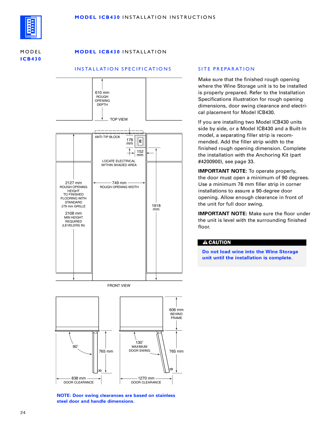
Make sure that the finished rough opening where the Wine Storage unit is to be installed is properly prepared. Refer to the Installation Specifications illustration for rough opening dimensions, door swing clearance and electri- cal placement for Model ICB430.
If you are installing two Model ICB430 units side by side, or a Model ICB430 and a
IMPORTANT NOTE: To operate properly,
the door must open a minimum of 90 degrees. Use a minimum 76 mm filler strip in corner installations to assure a
IMPORTANT NOTE: Make sure the floor under the unit is level with the surrounding finished floor.
Do not load wine into the Wine Storage unit until the installation is complete.
90˚
FRONT VIEW
606 mm
BEHIND
FRAME
| 130˚ |
|
| MAXIMUM |
|
765 mm | DOOR SWING | 765 mm |
![]() 838 mm
838 mm ![]()
DOOR CLEARANCE
![]() 1270 mm
1270 mm ![]()
DOOR CLEARANCE
NOTE: Door swing clearances are based on stainless steel door and handle dimensions.
24
