Manuals
/
Sun Microsystems
/
Computer Equipment
/
Server
Sun Microsystems
CP3220
manual
Part number label
Models:
CP3220
1
33
135
135
Download
135 pages
63.69 Kb
30
31
32
33
34
35
36
37
Physical Characteristics A-1
Install
Blade Server Diagram
Connecting External I/O Cables
Warranty
Software Configuration
Using Unix Commands
Connectors and Pinouts
Navigating Bios Screens
Service Procedures
Page 33
Image 33
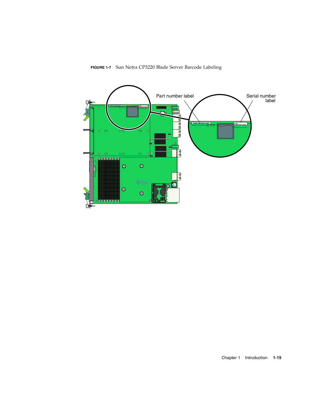
FIGURE
1-7
Sun Netra CP3220 Blade Server Barcode Labeling
Part number label
Serial number
label
Chapter 1 Introduction
1-15
Page 32
Page 34
Page 33
Image 33
Page 32
Page 34
Contents
Sun Netra CP3220 Blade Server User’s Guide
Please Recycle
Contents
Hardware Installation and Service
Software Configuration
Configuring and Using Bios Firmware
Physical Characteristics A-1
Viii Sun Netra CP3220 Blade Server User’s Guide January
Figures
Figure A-1
Figure B-18
Xii Sun Netra CP3220 Blade Server User’s Guide January
Tables
Xiv Sun Netra CP3220 Blade Server User’s Guide January
How This Document Is Organized
Preface
Shell Prompts
Using Unix Commands
Related Documentation
Typographic Conventions
Documentation, Support, and Training
Third-Party Web Sites
Sun Welcomes Your Comments
Introduction
Overview
Features
Front Panel Components
Physical Description
1Sun Netra CP3220 Dual-Core Blade Server Front View
2Sun Netra CP3220 Quad-Core Blade Server Front View
3Sun Netra CP3220 Blade Server Component Side View
Blade Server Diagram
AMC Modules
System Configurations
8Sun Netra CP3220 Blade Server User’s Guide January
Advanced Rear Transition Module
Out-of-service OOS LED Blue Hot Swap LED
10Sun Netra CP3220 Blade Server User’s Guide January
Artm
1I/O Configurations
Hot-Swap Support
System Components
Required Hardware Components
Software Components
Optional Hardware Components
Locating the Blade Server Identification Information
Technical Support and Warranty
Part number label
16Sun Netra CP3220 Blade Server User’s Guide January
Hardware Installation and Service
Equipment and Operator Safety
Safety and Tool Requirements
Installing the Blade Server
Preparing for the Installation
Materials and Tools Required
1.2, Local Network IP Addresses and Host Names Worksheet on
Check Power, Thermal, Environmental, and Space Requirements
1Local Area Network Information
Local Network IP Addresses and Host Names Worksheet
Installation Procedure Summary
Configuring the Hardware
Installing Optional Components
Verify Chassis Fan Tray Upgrade
Installing an Advanced Rear Transition Module
Configuring the Advanced Rear Transition Module Hardware
1Installing the Sun Netra CP32x0 Artm
To Install an Artm
2Injector/Ejector Latch and Locking Screw on the Artm
Installing the Blade Server Into the Shelf
Connecting Cables to a System Console Running the Solaris
Connecting External I/O Cables
Tip utility Minicom utility
2Netinstall Boot Device Table
Netinstall Boot Device Map
3Extra MAC Addresses for Virtual LAN Configuration
Service Procedures
Powering Off the Sun Netra CP3220 Blade Server
Hot-Swapping the Sun Netra CP3220 Blade Server
Powering On the System
Automatic Power-Off Events
Removing the Sun Netra CP3220 Blade Server
Dimm Requirements
Servicing DIMMs
Pair
Installing a DDR2 Dimm
Removing a DDR2 Dimm
5Installing a Dimm
6Removing a Dimm
Locate the Compact Flash connector
Installing the Optional Compact Flash Card
7Compact Flash Location
Installing Optional AMC Cards
8Removing an AMC Filler Panel
9Installing an AMC Card
Adding or Replacing a TOD Clock Battery
Changing Jumper Settings
Clearing the Cmos Setting Using Jumper
4Pin Functions on Jumper
10Jumper 1 in the Run Position
AMC slot B1 Jumper Pin Zone Connectors
Changing the OOS LED Color
Changing OOS LED Behavior
Hardware Installation and Service
At the clia CLI, enter the Get Ipmi Control Bits command
Viewing OOS LED Settings
At the clia CLI, enter the Set Ipmi Control Bits command
Setting OOS LED Behavior
13Sun Netra CP3220 Blade Server Front Panel
Resetting the Sun Netra CP3220 Blade Server
Software Configuration
Operating Systems
Software Updates
SunVTS Software
Configuring Sun Netra CP3220 For 1GbE or 10GbE Switches
Configuring Alternate OOS LED Behavior
Displaying Configuration of OOS LED Behavior
Setting Configuration of OOS LED Behavior
8Sun Netra CP3220 Blade Server User’s Guide January
Configuring and Using Bios Firmware
Navigating Bios Screens
About Bios Settings
Bios Considerations
Bios Option ROMs on the Sun Netra CP3220 Blade Server
AMD PowerNow! Feature Enabled by Default
Description of the Bios Screens
Otherwise, go to Step
Changing the Configuration of a Bios Menu Item
Setting the Boot Device Using Bios Setup Screens
Boot Settings menu is displayed Figure
2Boot Settings Menu
3Boot Device Priority Menu
Setting Supervisor and User Passwords
Changing the Bios Continuous Boot Setting
Security Settings Menu Change Password Menu
Resetting the System Time and System Date
Updating the Bios
Secondary Bios Image
Use the Secondary Bios Image
For example
Perform a Live Firmware Upgrade
Changing Post Options
Power-On Self-Test
2POST Options
16Sun Netra CP3220 Blade Server User’s Guide January
Hardware Architecture
1Block Diagram
Block Diagram
AMD Opteron Processor
Memory
2AMD Opteron Processors Block Diagram
NVidia MCP55
Networking and I/O
PCI Express Bus
Dual Bios
Trusted Platform Module TPM
Broadcom 5715C Gigabit Ethernet
AMC Slots
I/O Components
3 SAS/SATA
EIDE/ATA for Compact Flash
Physical Characteristics
Power and Thermal Metrics
Form Factor
Processor Metrics
Picmg Artm Cooling Requirements
Picmg Board Cooling Requirements
Table A-1Airflow Requirements
Table A-2ARTM Pressure Drop
Connectors and Pinouts
Front Panel Connectors
Ethernet Port
Table A-4USB Port Pin Assignments
USB Ports
Power Connector Zone
AMC Connectors
Front Panel Serial RJ-45 Connector
Table A-5Serial Port Mini DIN 8-pinConnector Pinouts
Table A-6Power Distribution Connector Pin Assignments
Figure A-4Power Distribution Connector Zone 1 P10
Scla
Figure A-5Zone 2 Connector
Data Transport Connector Zone
Table A-7Zone 2 Connector Pin Assignments
Advanced Rear Transition Module Connector Zone
Table A-8J31 Connector Pin Assignments
Table A-10J33 Connector Pin Assignments
Table A-9J32 Connector Pin Assignments
Bios Screens
ROM
Bios Menu Tree
Figure B-2
Bios Main Menu Advanced Configuration Menu
Figure B-4
CPU Configuration Menu IDE Configuration Menu
Figure B-6
Super IO Configuration Menu Acpi Settings Menu
Figure B-8
Event Logging Details Menu MPS Configuration Menu
Figure B-10
PCI Express Configuration Menu Smbios Configuration Menu
Figure B-12
Remote Access Configuration Menu USB Configuration Menu
Figure B-14
Advanced PCI/PnP Settings Menu
Figure B-16
Boot Settings Menu Boot Settings Configuration Menu
Boot Device Priority Menu Boot Hard Disk Drive Priority Menu
Figure B-20
Security Settings Menu Change Password Settings Menu
Figure B-22
Chipset Main Menu NorthBridge Chipset Configuration Menu
Figure B-24
Figure B-26
Figure B-28
Hyper Transport Configuration Menu Exit Options Menu
Appendix B Bios Screens
Index
Bios
Post
Index-3
Index-4Sun Netra CP3220 Blade Server User’s Guide January
Top
Page
Image
Contents