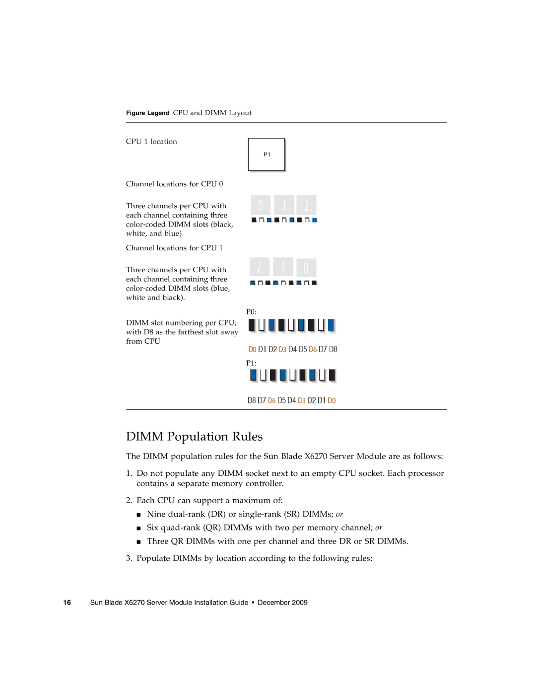
Figure Legend CPU and DIMM Layout
CPU 1 location
Channel locations for CPU 0
Three channels per CPU with each channel containing three color-coded DIMM slots (black, white, and blue)
Channel locations for CPU 1
Three channels per CPU with each channel containing three color-coded DIMM slots (blue, white and black).
P0:
DIMM slot numbering per CPU; with D8 as the farthest slot away from CPU
P1:
DIMM Population Rules
The DIMM population rules for the Sun Blade X6270 Server Module are as follows:
1.Do not populate any DIMM socket next to an empty CPU socket. Each processor contains a separate memory controller.
2.Each CPU can support a maximum of:
■Nine
■Six
■Three QR DIMMs with one per channel and three DR or SR DIMMs.
3.Populate DIMMs by location according to the following rules: