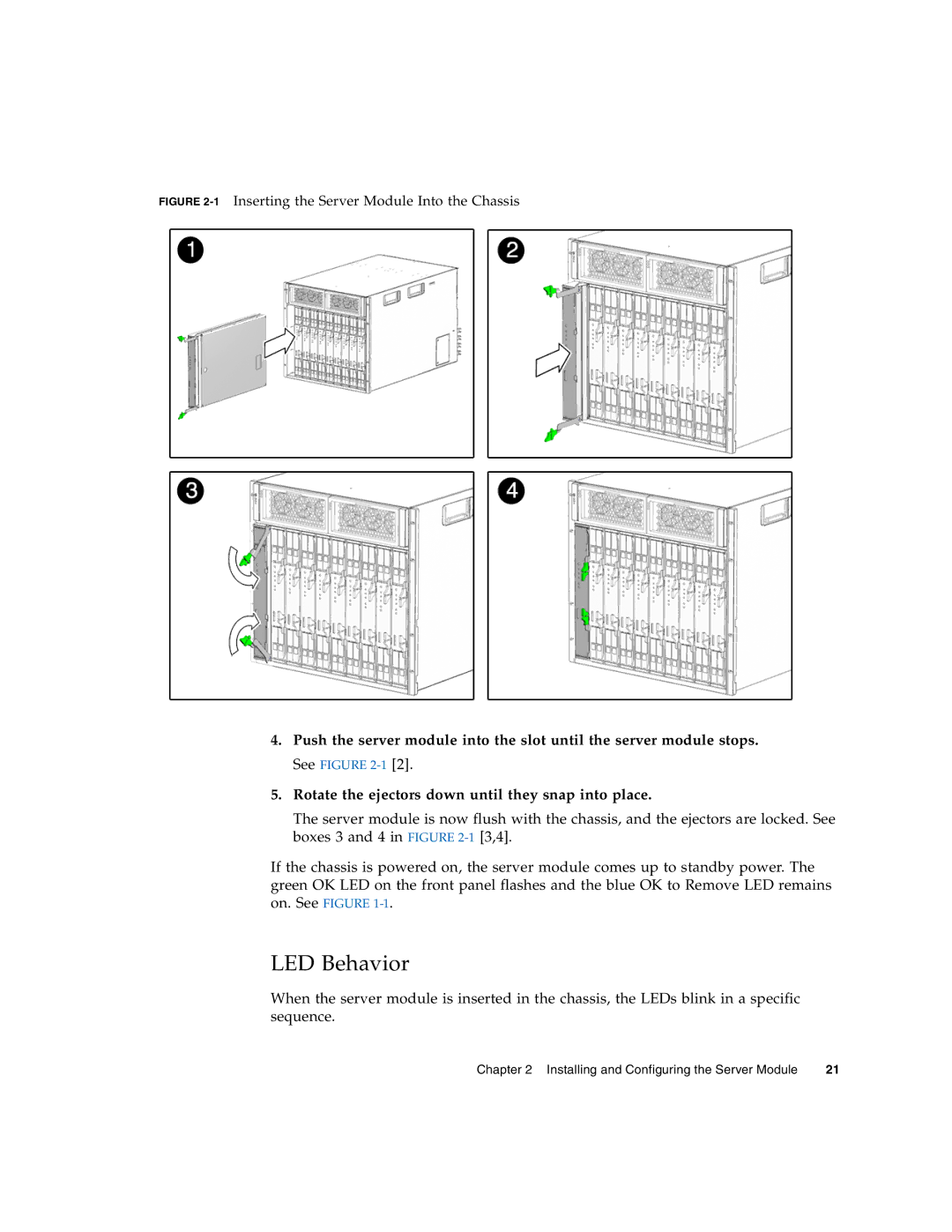
FIGURE 2-1 Inserting the Server Module Into the Chassis
4.Push the server module into the slot until the server module stops.
See FIGURE
5.Rotate the ejectors down until they snap into place.
The server module is now flush with the chassis, and the ejectors are locked. See boxes 3 and 4 in FIGURE
If the chassis is powered on, the server module comes up to standby power. The green OK LED on the front panel flashes and the blue OK to Remove LED remains on. See FIGURE
LED Behavior
When the server module is inserted in the chassis, the LEDs blink in a specific sequence.
Chapter 2 Installing and Configuring the Server Module | 21 |