XLi Ieee 1588 Clock
Page
Table of Contents
User Interfaces
SSS Ssssssssssssssssss Sssssssssssssssssss
XLi-Generated Messages
Snmp
Viii
Description
Standard Configuration
Overview
Ieee 1588 Subsystem
Related Specifications
Ieee 1588 card
Physical
Behavior
Network Port
PPS Output Sync OUT
User Interface
Introduction
GPS C/A Receiver
LEDs
Related topics
Specifications
Standard Tcvcxo Oscillator
Standard 110 VAC Power Supply
Clock Architecture
DAC
Interface Architecture Block Diagram
AC Power Supply
Mechanical/Environmental
GPS Receiver
System Time & Frequency Accuracy
Chassis
Aux Ref Input
NET Network Port
Standard Inputs and Outputs
Serial I/O Port
J1 Input Time Interval Event Time
J2 Output Rate Out
Code Time Code Output
J3 Input Auxiliary Reference
PPS Pulse Per Second Output
Auxiliary Reference Aux Ref
Alarm Output
Certifications
Installing the GPS Antenna
Selecting a GPS Antenna Site
Verifying the Site
Mounting the GPS Antenna
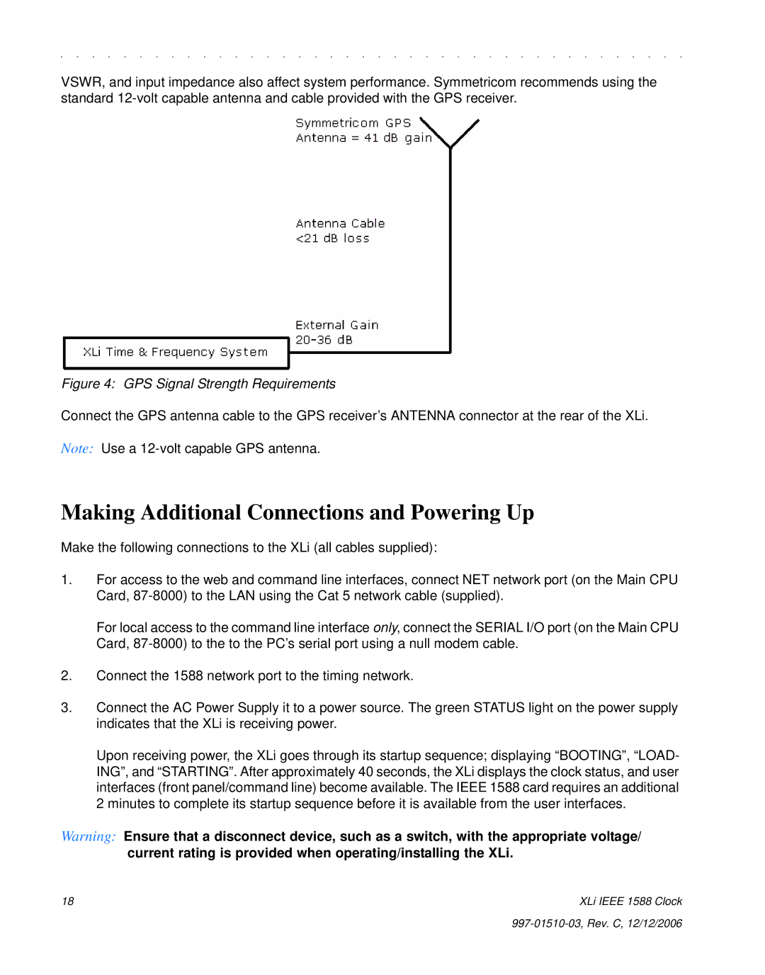
GPS Signal Strength Requirements
L1 GPS Antenna methods for cabling and mounting
Making Additional Connections and Powering Up
GPS Signal Strength Requirements
Configuring Network Settings
Configuring the XLi
Configuring the Ieee 1588 Cards
PTP Master
PTP Slave
Slave Sync Threshold 5 microsec
Rack Mounting the XLi
Secure the brackets to the rack using rack mount screws
997-01510-03, Rev. C, 12/12/2006
Time Display
Alarm Status LED
Keypad/Display Interface
Where
Status Display
Menu Display
Locked ∗ GPS PRI UTC
Keypad Operation
Time Zone Offset
Other ways to abandon new settings in a function
To open a function using Menu
To change the settings in a function, and not save them
Keypad Examples
Guest Login
Command Line Interface
Operator Login
Logging
You can log out using any of the following commands
Changing Username and Password
Session Timeout and Priority
Logging Out
Network port session
Web Interface
User Privileges
Navigating
User Names and Passwords
Sessions
Submitting Changes
997-01510-03, Rev. C, 12/12/2006
Function Reference
Function Summary
Snmp
F100 K I L L Reboot
F1SSIGNHHMMCRLF
F1 Time Zone Offset
For example, to set the time zone offset, enter
Sign
To verify the change, enter
F2 12/24 Hour Format
XLi responds
Separately from
To set the hour format, send
F3 Time & Date
For example, to display the current hour format, send
F2SDHHSEPIHHCRLF
F3CR
Time Mode =
To display the time and date, send
SEP
For example, to display the date and time, send
F4 Serial Port Configuration
To display the Serial Port settings, send
To set the time and date, send
To set the serial port settings, send
F5 Time-Quality Setup
For example, to display the serial port settings, send
F4 232 9600 8 none 1CRLF
F5SSTATESEPFLAGSEPFLAGSEPFLAGSEPFLAGCRLF
XLi responds The XLi responds
F5CR
To display the Keypad Lock status, send
F5 Enable 2000 20000 200000 2000000CR
F6 Keypad Lock
F6CR
F8 Continuous Time Once-per-Second
To enable Keypad Lock, send the following string
To disable Keypad Lock, send the following string
For example, to display the Keypad Lock status, send
Format of the F8 Output String
F5 Time-Quality Setup F11 Time Output Format F69 Time Mode
Factory setting for the output string format is as follows
Sohdddhhmmssqcrlf
XLi replies
While Synchronizing to a Reference Source
After Loosing a Reference Source
F8CR
SOHDDDHHMMSS.mmmQCRLF
F9 Time On Request
For example, to prepare Time on Request, enter
To exit F9 press Ctrl-C on your keyboard
To display the default format for F11, enter
F11 Time Output Format
F11 responds
F11, with DDD suppressed, responds
When you check the results by entering F11, F11 responds
To see the resulting change to F11, enter
F11 D
With the new formatting, F8 displays
F13 Time Error
For example, to display the time error, enter
F9 displays
F18 Software Version Request
F18CR
F50 B1 Llacr
For example
F51 GPS Antenna Cable Delay
XLi responds using the following format
F50 B1 Xyzcr
F51SBNCR
F51SBNSEPSIGNDELAYnsCRLF
Delay
F51 B4CR
F52SEPSIGNDELAYnsCRLF
F52 Distribution Cable Delay
To display the current distribution cable delay, enter
F51 B4 100NSCR
F52 +000000nsCRLF
F53 GPS Operation Mode
To set the distribution cable delay to 60 ns, enter
F52 +000060nsCR
To save changes, press Enter
F53 responds using the following format
If an GPS C/A Receiver is available, F53 displays
For example, enter
Example response
Or Dynamic Mode
F60 GPS Receiver Satellite List
F53 responds
F60 B1 Allcr
Type
Level
F60 B1 Currentcr F60 B1 Trackedcr
F66CR
F66 Daylight Saving Time DST Mode
For example, to disable DST, enter
F66 OffCR
F66 Manual 02 1 1 04 02 0 1
Where
XLi responds to all changes with
F66 Manual 0 CR
F69 Time Mode
Important interactions between F69 and the IEEE1588 card
F69CR
Related functions
XLi gives one of the following responses
F69 Local Crlf F69 Standard Crlf
To display the F71 settings, enter
For example, to change the time mode to local time, enter
Or, to change the time mode to UTC, enter
F71 Oscillator Statistics
EXP
F72 Fault Status
To display the status of the fault detectors, enter
DAY
F73 Alarm Control / Status
F72CR
DAC
Alarms General Information
F73SSSTATUSSOURCES123456789ABCDECRLF
GPS PRI OK Alarm Enabled
F73CR
Source
F73SMASKSEPM12346789ABCDECRLF
To clear the Alarm Latches, enter
F73SLATCHSEP123CRLF
F73SMASKSEP123456789ABCDECR
For example, to enter new mask settings, enter
XLi replies To verify the changes, enter
To enable LED Blink, enter
To view the Time Threshold setting, enter
To view Timeout Delay, enter
To disable LED Blink, enter
F74 Clock Source Control
XLi responds, using the following format
F90 Code Output Configuration
To display the current settings, enter
F74CR
F90SCODE Outputtypecr
To change the Code Output selection enter
F90CR
Code Output
F100 Network Port Configuration & XLi Firmware
Group
Description F100 followed by Comments
F100 Eacr
F100 EA Ethernet Address
F100 IP IP Address
F100SIPCR
F100 Ipcr
F100 SM Subnet Mask
F100 IP 206.54.0.21CR
F100 IP 192.169.46.150 SM255.255.255.0 G 192.168.46.1CR
F100 G Gateway
F100 G 206.54.0.17CR
F100 IC Network Port Settings
F100 Baset 10/100 BASE- T
F100 GCR
F100 Baset 10TCRLF
OK Crlf Reseting the Unitcrlf Please WAIT…CRLF
F100 L/LOCK/UNLOCK Remote Lockout
Or use the keypad/display’s F100
F100 L Remote Lockout
To users on the serial port, XLi responds
GOODBYE.CRLF
F100SSTCR
F100 ST Self Test Status
F100 L Lockedcrlf F100 L Unlockedcrlf
F100 BH 10.1.7.20 truetime/xli/192-8001.binCR
F100 BUB Burn BootLoader
F100 BH Burn Host
F100 Bubcr
F100 BU Burn
And, for example, displays the following text
F100 Bucr
F100SBFCR
F100 BF Burn File System
F100 Bufp Burn Fpga Firmware
F100 bf Burning File 192-8002.fs with Size 524288 SEC
F100 Config Configure NTP & Snmp
Flash Successfully Programmed
F100 config snmp get hostIP Address dirsubdirCR
F100 J Factory Mode Jumper
Here’s an example of a successful Snmp config file transfer
F100 config snmp set hostIP Address dirsubdirCR
F100 J Factory MODE=1CRLF F100 J Factory MODE=0CRLF
F100 K I L L Reboot
F100SJCR
F100 Ksislslcr
Scanforoptcard Begins
F100 P Change User Password
Flash File System Mounted
Initialization Successfully Completed
Unit responds example
When you enter the new password, the XLi responds
F100 PI Ping
F100 Pisip AddressCR
Or it responds
When you enter a new user name, The XLi responds
F100 PN Change User Name
F100 Picr
High High Stability Ocxo
F108 Oscillator Configuration
F108SOSCILLATORSCONFIGSOSCCRLF
F108SCR
For example, enter the following string
F108 Oscillator Config Tcvcxocrlf
F110 J1 Input Tiet
OSC =
Function responds with the Ascii character string
F110CR
Tiet
To obtain Tiet measurement from J1, enter
Then configure Tiet example
F111 J2 Output Rate
F110 Tiet 50 Positivecrlf
Displays a fixed 10 PPS rate output example
To request the J2 Output Configuration, enter the following
XLi responds in the following format
F111CR
Auxiliary Reference Aux Ref Input
F113 J3 Input Configuration Aux Ref
For example, to produce a fixed 100 kPPS rate output, enter
Where the F113 entry and request formats are defined as
To display the J3 Input Configuration, enter
XLi responds using the following formats
XLi displays the current configuration example
F116 Display Brightness Level
Or, to disable F113, enter
F113 Disablecrlf
To all of the above examples, the XLi responds
NTP
F117 Factory Configuration
F117CR
Freq Meas =
F118 Option Board Configuration
F118SBNCRLF
F118 B1CR
F118SBNSOCCRLF
OC =
F118 B1 GPS M12 Receiver
F119 GPS Receiver Configuration
This information is useful for identifying the option card
233182129
Unlocked GPS PRI Local
Locked GPS PRI Local
To obtain the status of the GPS Receiver, enter
F119SBNSEPSCR
F119SBNSCCR
F119SBNSCSCONFIGCR
F119 B1 S
F119 B1 CCR
For example to make it a primary reference source, enter
F119 B1 C Pricrlf
F126SKCCRLF
F126 Options Key Entry
F128 Have Quick Output
F126S5674397586090CR
F130 Precision Time Protocol Status
PTP Technology Ethernet PTP NO. of Ports PTP Stratum
F130SPBNSEPS
PTP Part Number
118 XLi Ieee 1588 Clock
F131 Precision Time Protocol Network Config
Option bay location of the Ieee 1588 cards
Dhcp enabled/disabled
PTP Sync message interval
Reset PTP settings to factory defaults
PTP burst mode enabled/disabled
PTP network port enabled/disabled
PTP subdomain same
PTP Slave Synchronization Threshold
PTP Preferred Master Configuration
PTP Master or Slave PRI/SEC/STBY
Error Invalid Command
F131 BN F131 B4
Enable/disable Dhcp
Set the Default Gateway
Request the Dhcp settings
Request the PTP Protocol settings
Request a summary of the PTP card configuration
Set Internet Configuration settings
Set the IP Address
Set the Subnet Mask
To set the Default Gateway, enter
Set the Default Gateway
To get the Default Gateway, enter
To get the Dhcp setting, enter
Setting the Internet Configuration
Enable/Disable Dhcp
Response
To set the PTP protocol settings, use the following format
Get PTP Protocol settings
To get PTP protocol settings, use the following format
F131 B4 Protocol 27 Enable Enablecrlf
To request the PTP Subdomain Name, use the following format
Request the PTP Subdomain Name
Set the PTP Subdomain Name
To set the PTP Subdomain Name, use the following format
Reset the PTP Parameters to the Factory Default settings
Initialize the PTP Protocol to User-entered Values
F131 BN CCR
Configuring the PTP Reference Clock Settings
To change the settings, use the following format
F131 B4 C
F131 BN Sstcr
Request the PTP Slave Synchronization Threshold
Set the PTP Slave Synchronization Threshold
F131 B4 SST
Request PTP Network Parameter Status
Request the PTP Preferred Master Clock Configuration
F131 B4 PM Enablecrlf
F131 B4 PM
F131 B4CRLF
Preferred Master Enablecrlf
F131 B4 S
Slave Sync Threshold 5 microsecCRLF
136 XLi Ieee 1588 Clock
Error Messages
XLi-Generated Messages
Error Action get or set is not specified
Source file was successfully read
Host configuration was successful
Informational Messages
XLi has just terminated a session
This page was intentionally left blank
Overview of Steps
Configuring Snmp Parameters
Set up the FTP Server
Get the IP Address of the FTP Server/Workstation
F100 config snmp get hostIP Address dirsubdir
Copy the Configuration Files to the FTP Server
Edit the Configuration Files
Move the Configuration Files Back to the XLi
F100 config snmp set hostIP Address dirsubdir
144 XLi Ieee 1588 Clock
Overview of Procedure
Open a Command Line Session on the XLi
Upgrade the Firmware
Enter the following command
Then do the same for the ‘file system’ .fs file
Do the same for the ‘firmware’ .bin file
Then enter
F100 bh 192.168.49.120 /192-8002.fs
Troubleshooting
Then enter K space I space L space L as shown here
F100 bf
An example XLi response is
Log on to the XLi and enter the following command
Bootloader
Nvram VER Proj REV
F100 IC F100 IP192.168.47.156 SM255.255.255.0 G192.168.47.1
SymmetricomTtm-SMIv2.mib
152 XLi Ieee 1588 Clock
Syntax Integer 0..2147483647 MAX-ACCESS read-only
154 XLi Ieee 1588 Clock
XLi Ieee 1588 Clock 155 997-01510-03, Rev. C, 12/12/2006
TSP
DCN
Nist
DTS
Syntax Integer 0..8 MAX-ACCESS read-only Status deprecated
GpsLongitude OBJECT-TYPE
Baud300 300, baud1200 1200, baud9600
Syntax Counter32 MAX-ACCESS read-only Status deprecated
160 XLi Ieee 1588 Clock
Organization Symmetricom INC CONTACT-INFO
XliMainCard-SMIv2.mib
END
NoLeapWarning
= ntp NtpEstErr OBJECT-TYPE
Syntax Integer
Field, ntpSysStratum, to 1. = ntp
Syntax Integer -127..127 MAX-ACCESS read-only Status current
MODULE-IDENTITY
Xli-SMIv2.mib
XliSystem-SMIv2.mib
SystemFaultHistory
SystemAlarmData
SystemFaultConfig
SystemFaultConfigData
LatchClear
168 XLi Ieee 1588 Clock
XLi Ieee 1588 Clock 169 997-01510-03, Rev. C, 12/12/2006
170 XLi Ieee 1588 Clock
XLi Ieee 1588 Clock 171 997-01510-03, Rev. C, 12/12/2006
172 XLi Ieee 1588 Clock
ClockIrigA
Unlocked1 Locked MAX-ACCESS read-only
Locked1 Unlocked2
= systemStatusGeneral
Fault
Gives the current status of the IRIG. = systemStatusDetail
StatusSecondaryPower OBJECT-TYPE Syntax Integer
Ok 1, fault 2 MAX-ACCESS read-only Status current
Editing snmp.conf
New Top Level Structure of Enterprise MIB for XLi
Snmp Private Enterprise MIB Structure
Snmp Addressing
Key
Additional Products
XLi System Group
XLi Fault Group
XLi System Status Group
XLi MainCard Group
XLi Traps
Future Expansion
Glossary of SNMP-Related Terms
XLi unit PC with HP OpenView installed
Configuring and Testing Snmp
HP OpenView Configuration
Materials Needed
Configure Traps
Load the TrueTime Enterprise MIBs
XLi Configuration
Test Procedure
Trap Testing
188 XLi Ieee 1588 Clock
Introduction
Irig Code Format
Input
IRIG-B Time Quality Flags
Output
Nasa 36 Code Format
Irig Standard Format a
World Map of Time Zones
194 XLi Ieee 1588 Clock
Part Numbers
Time Interval Event Time Tiet on Main CPU J1 87-8026
196 XLi Ieee 1588 Clock
Sales and Customer Assistance
Customer Assistance Center Telephone Numbers
198 XLi Ieee 1588 Clock
Glossary of Ieee 1588-related Terms
200 XLi Ieee 1588 Clock
Antenna
Alarm Status
Cable Delay
Have Quick Configuration
Code Output Configuration
Configuration
Error
F100 Config Configure NTP & Snmp Parameters
Guest Login User Name Password
Messages
Network Settings
Keypad
Network
Rate Output
Signal Strength Requirements
Oscillator
Serial Port
Snmp Private Enterprise MIB Structure
Standard 12 VDC Power Supply
Fault
Snmp.conf Editing
XLi
Username
Version