bed_anl_DIGITY CI_Quark3_en.qxd 31.01.03 16:47 Seite 37
>When you have entered the settings for the test transponder, press the Back key to return to the menu related to motor antenna settings. The field for entering the orbital position is active.
>Use the numeric keys to enter the orbital position of the satellite and confirm by pressing OK.
>Press the
position.
In the position
In the position
8.3.2 Adjusting the satellite antenna
To adjust the antenna correctly for the satellite selected, resp. to determine whether you can receive signals from the satellite selected at the position you have set, a test transponder setting is provided for each satellite.
The indication of signal strength and quality by this test transponder allows you to align the antenna precisely.
8.3.2.1 Test-Transponder/LNB-configuration
To change the data relating to the respective test transponder, proceed as follows:
>Use the arrow keys to select the entry Current
| satellite list. |
| |
> | Press the OK key to open the satellite list.> Use the |
| |
| arrow keys up/down to select the satellite position |
| |
| on which you wish to change data. |
| |
> | Confirm by pressing OK. |
| |
> | Now, use the arrow keys to select the field LNB |
| |
(Fig. | |||
|
|
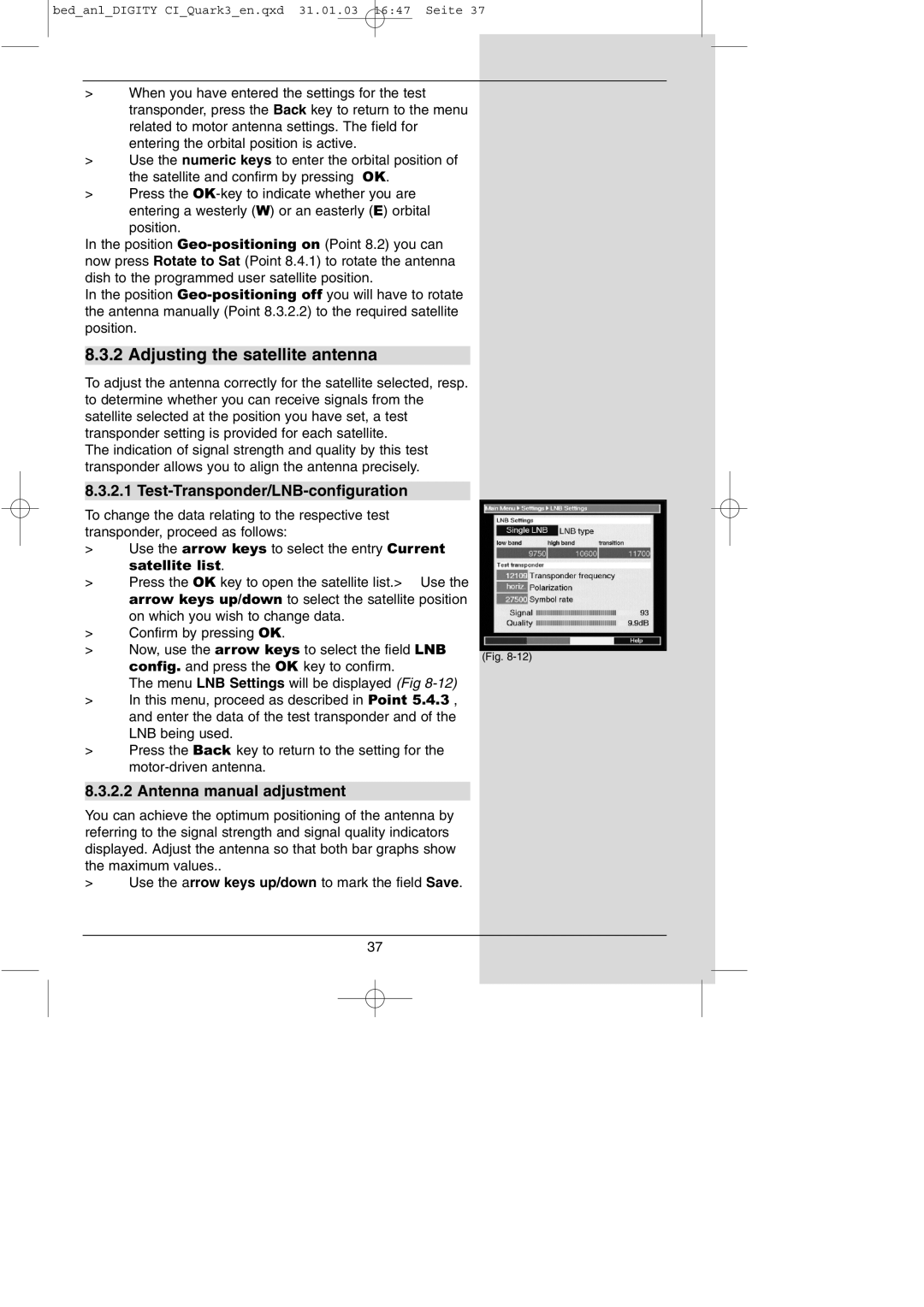
config. and press the OK key to confirm.
The menu LNB Settings will be displayed (Fig
>In this menu, proceed as described in Point 5.4.3 , and enter the data of the test transponder and of the LNB being used.
>Press the Back key to return to the setting for the
8.3.2.2 Antenna manual adjustment
You can achieve the optimum positioning of the antenna by referring to the signal strength and signal quality indicators displayed. Adjust the antenna so that both bar graphs show the maximum values..
>Use the arrow keys up/down to mark the field Save.
37
