1705A Spectrum Monitor SN B040000 and Above 070-8222-08
Table of Contents
Theory of Operation
Installation
Table of Contents
Checks and Adjustments
1705A Spectrum Monitor Iii
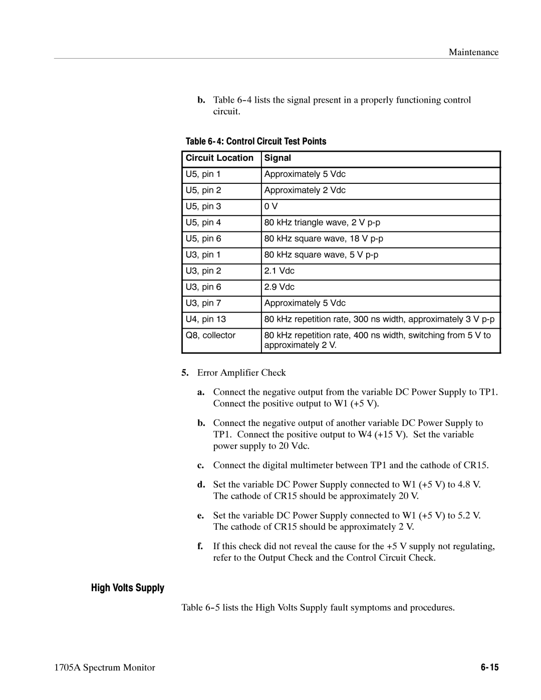
Maintenance
Options
Replaceable Mechanical Parts 10-1
Replaceable Electrical Parts
Replaceable Electrical Parts
List of Figures
Simulation of a 1705A Full SPAN/DIV display
Considerations for custom installation of an instrument
1705A Spectrum Monitor Vii
List of Tables
Viii
General Safety Summary
General Safety Summary
Service Safety Summary
Service Safety Summary Xii
Introduction
Installation
Preface
Replaceable Mechanical Parts
USA
Contacting Tektronix
Preface
Preface Xvi
Introduction
Page
Typical Configurations
Section Introduction
Accessories
Options
Introduction
#73
Safety Information
Optional Accessories
Full
Spectrum Display
SPAN/DIV
CRT Display
Power Source
Introduction Spectrum Display
Introduction Environmental Characteristics
Physical Characteristics
Certifications and Compliances
EMC
Introduction Certifications and Compliances
CAT
Meters
Applications
SUN Satellite
Earth
Using the 1705A for Satellite Communication
Band Input Signals
Vancouver BC Seattle Portland Helena Boise SAN Francisco
LOS Angeles
SAN Diego
Zeroing in on a Satellite
Tek 12.20 GHZ
Horizontal Vertical Polarization
Frequency and Number Down Link Transponder
Looking at Exciters with the 70 MHz Input
GHZ
Miscellaneous Uses for the 1705A
LNB OUT
Band
Splitter
Input
Operating Instructions
Page
Front-panel Controls and Indicators
Section Operating Instructions
Position Power
Operating Instructions
Filter Input
Display
Variable control that adjusts the display brightness
SPAN/DIV
Rear- Panel Connectors
Position
Holder for the instrument’s mains fuse
Spectrum Monitor
Powering- up
1400 MHZ
Measurement Graticule
1705A graticule scale
Reading in dB Voltage Ratio Power Ratio
Voltage Ratio Power Ratio
Operating Instructions DB Reference
Reading in dB
75Ω 50Ω
Operating Instructions DBm to v Conversion Reading in dBm
Frequency Scale = 10 Divisions Sweep Length = 12 Divisions
Minimum Maximum Frequency
MID
MHZ
Center Frequency Readout
70 MHZ
1400 MHZ
Point on Trace That Corresponds to
Center Frequency Tuned AT this Point
Customizing Frequency Readout
Readout Mode
Offset Adjust
Main Menu
Readout Position
12.00 GHZ
Basic Operating Procedure
Locating Ku- Band Satellites
City
Satcom K2 G-STAR
1705A Spectrum Monitor
Operating Instructions
Page
Page
Installation
Page
Section Installation
Electrical Installation
Mechanical Installation
Installation
LNB Power Band Input OFF
Cabinet Options
250
875
105
130
1700F02 portable cabinet dimensions
Cabinetizing
Cabinet Securing Screws
A WFM7F05 with a blank front panel 1700F06
1700F07
1705A Spectrum Monitor
Theory of Operation
Page
Overview
Block Diagram
Section Theory of Operation
Theory of Operation
Front Panel Diagram
RF Input Diagram
If Amplifier Diagram
Resolution Filter and Log Detector
Sweep Generator Diagram
Start Display
Deflection Amplifiers Diagram
Vertical Deflection Amplifier
Microprocessor Diagram
Front Panel Diagram
LOW Load Average
High Load
Low Voltage Power Supply Diagram
Pulse Width Modulator
Theory of Operation
High Voltage Power Supply Diagram
Axis Amplifier
CRT The pinout for the CRT is shown in Figure
Pinout of the CRT Socket 1705A Spectrum Monitor
Theory of Operation
Checks and Adjustments
Page
Electrical Instruments
Section Checks And Adjustments
Recommended Equipment List
Auxiliary Equipment
Performance Check
Short-Form Procedure
Checks and Adjustments SMA Male-to-bnc Female Adapter
1705A Spectrum Monitor
Long Form Procedure
Checks and Adjustments Preliminary Control Settings
Page
Marker Here Marker is +/-- 1 Minor Division from Here
Checks and Adjustments
1705A Spectrum Monitor
Page
Variable Autotransformer L-BAND Input
Disregard
Marker Here Graticule Line
UHF Sine Wave Generator
Page
End of the Performance Check Procedure
Adjustment Procedure
Short- Form Procedure
Preliminary Setup
Video SPAN/DIV Full Center Frequency
A1 PWR Sply BD
A3 Main BD
Front
Tek
Strap
Remove the shorting strap 1705A Spectrum Monitor
Shorting
1705A Spectrum Monitor
Page
1705A Spectrum Monitor
Page
1705A Spectrum Monitor
End of Adjustment Procedure
Checks and Adjustments
Maintenance
Page
Section Maintenance
Cleaning
Schottky Signal
LOW Power Schott
Cmos
ECL
Troubleshooting
Diagnostic Routines
Nonvolatile 2444 RAM Test
Reading Data Stored AT 60H to 7F in Processor
Error Cannot Read or Write Press Input KEY to Exit
Troubleshooting Aids
Circuit board assembly locations
Major Assembly Interconnection
ROW B ROW a
PIN
Power Supply Troubleshooting Procedure
Power Supply Fault Symptoms
Maintenance Power Supply Fault Symptoms
Low Volts Supply
Maintenance Rectifier/Switcher Check
High Volts Supply
Maintenance High Volts Supply Fault Symptoms
Focus Amplifier Check
Axis Amplifier Check
Grid Drive Check
High Voltage Oscillator Check
CRT Voltage Check
Corrective Maintenance
Obtaining Replacement Parts
Bezel Removal
Mechanical Disassembly/Assembly
Maintenance Test Selectable Components
Graticule Light Removal and Replacement
Removal of the CRT
Replacing the CRT
Removal of Front- Panel Assembly
Removal of the Rear Panel
Removing the L- Band Tuner
Removal Replacement of the Main Board
Removal Replacement of the Power Supply Board
Removing the LNB Power Supply Board
Front
Repackaging
1705A Spectrum Monitor
Options
Page
Field Upgrade Kits
Power Cord Options
Power Cord Options Description of power cord
Section Options
Ordering
Replaceable Electrical Parts
Page
Parts Ordering Information
Using the Replaceable Electrical Parts List
Section Replaceable Electrical Parts
Column Descriptions
Tektronix Part No
Column
Column 3
Spectrum Control INC Weight ST
Cross Index MFR. Code Number to Manufacturer
AMP INC Fulling Mill Harrisburg PA
MSD INC Orange ST DARLINGTON, SC
Zman & Associates
Sobudai Zawa Kanagawa 228 Japan
Chrome Shibaura Tokyo Japan 2ND Floor NEW Kyoei MINATO-KU
Wilhelm Westerman
Circuit BD Assypower SUPPLY, 1705A
Circuit BD ASSY18V Power Supply
Circuit BD Assyfront Panel
Circuit BD Assymain Board ASSY,1705A
IAL,MI
CAP,FXD,PLSTC100PF,5%,1600VDC/500VAC
IN,BULK
CAP,FXD,CER DI470PF,20%,100V TUBULAR,MI
LAMP,GLOW135V MAX,1.9MA,C2A-T,WIRE Lead
A1DS1
A1DS2
A1DS3
SQ,TOP Adjustbulk
SQ,SIDE ADJUSTT&R
RES,FXD,CMPSN1.5M OHM,5%,1W
RES,FXD,CMPSN2.2M OHM,5%,0.5W
RES,FXD,FILM5K OHM,0.1%,0.2W,TC=T9
IAL,T&R,SMALL Body
REELED,SMALL Body
RES,FXDMETAL FILM,100K OHM,1%,0.2W,TC=100
SQ,TOP ADJUST,T&R
WIRED,1705A
RES,THERMAL5 OHM,10%,7A/DEG C
RES,FXD,CMPSN2.4K OHM,5%,2W
LED ASSYDIR1
Part of A2DS313
CA ASSY,SP,ELEC34,26 AWG,5.0 L
RES,VAR,PNLCP,20K OHM,20%,0.5W,LINEAR,W
BUS,CNDCT
PLATE,ELEC Shldcircuit Board
SHIELD,ELECCIRCUIT Board
SHIELD,ELEC1705A,BRS
CAP,FXD,ELCTLT33UF,+50-20%,35WVDC
UVX1H330MAA
CAP,VAR,CER DI9-45PF,200V
CAP,VAR,PLSTC1-3.5PF,500V
CAP,FXD,MICA DI98PF,5%,500V
A3CR1
A3CR2
DIO,SIGFAST RCVRY70V,200MA,100NS,COM
A3FL1
FLTR,BANDPASS
A3FL2
A3FL3
COIL,RFFIXED,45NH
COIL,RFFIXED,15NH
COIL,RFFIXED,64UH
COIL,RFFIXED,505NH
RES NTWK,FXD,FI10K OHM,20%,9RES
ADJUSTT&R
GF06UT 2K
GF06UT 5K
RES,FXD,FILM3.4K OHM,1%,0.2W,TC=T0
RES,FXD,FILM115K OHM,1%,0.2W,TC=T0
RES,FXD,FILM237K OHM,1%,0.2W,TC=T0
RES,FXD,FILM7.5K OHM,1%,0.2W,TC=T0
RES,VAR,NONWWTRMR,250 OHM,20%,0.5W LIN
RES,FXD,FILM1M OHM.1%,0.2W,TC=T0
Percent
CRB20FXE1K62
CRB20FXE9K35
RES,FXD,FILM2.1K OHM,1%,0.2W,TC=T0
RES,VAR,NONWWTRMR,100 OHM,20%,0.5W LIN
RES,FXD,WW6.3K OHM,1%,3W
CRB20FXE210E
GF06UT 1K
RES,FXD,FILM187K OHM,1%,0.2W,TC=T0
Loss 10DB,PKG 7.2MM SQ,6.8MM HI
IC,CONVCMOS,A/D8-BIT,32US,SAR,DIFF IN,SER
MICROCKT,DGTLMICROCOMPUTER,8 BIT
IC,MISCCMOS,ANALOG Swquad SPST,100
IC,LINBIPOLAR,AMPLRF AMP,20DB
IC,DGTLTTL,BFR/DRVRHEX INV, OC, HI
MIXER,FREQ1-500MHZ
CONN,BOXSHUNT/SHORTINGFEM,STR,1 X 2,0.1
CTR,0.385 H,30 GLD,BLK,JUMPER
TAIL,30 GLD
IAL,MI,T&R
RES,FXD,FILM267K OHM,1%,0.2W,TC=T0
RES,FXD,WW1 OHM,5%,2W
Order by Desc
RES,FXD,CMPSN1K OHM,5%,0.50W
CONN,HDRPCB/WIREWRAP,MALE,STR,1 X 7,0.15
CONN,HDRPCB/WIREWRAP,MALE,STR,1 X 4,0.150
CORE,EMTOROID,FERRITE
COIL,RFFIXED,150NH
A10SKT1
Controlled 0LUA3
CONN,RF Plug
CA ASSY,SP
Replaceable Electrical Parts
Diagrams/Circuit Board Illustrations
Page
Diagrams/Circuit Board Illustrations
Symbols
Assembly Numbers
Component Values
Page
1705A Spectrum Monitor
With cross-references to schematic diagrams 1, 2, 3, 4,
A3 Main Board Component Locator
A3 Main Board
A5 70 MHz Tuner Board
Schematic Diagram 1 Component Locator Chart
Local Oscillator
1705A Spectrum Monitor RF Input
Schematic Diagram 2 Component Locator Chart
Resolution Filter & LOG Detector
1705A Spectrum Monitor If Amplifier
Schematic Diagram 3 Component Locator Chart
Band Linearity
Ramp Generator
Marker
Generator
Schematic Diagram 4 Component Locator Chart
Deflection
Amplifier
Filter
Buffers
Schematic Diagram 5 Component Locator Chart
1705A Spectrum Monitor
Microprocessor
Microprocessor
Trace
Schematic Diagram 6 Component Locator Chart
1705A Spectrum Monitor Front Panel & 18V Supply
A2 Front Panel Board
See Parts List for Effective Serial Number Ranges
A1 Power Supply Board
A1 Power Supply Board Component Locator
Switcher
Error
Line Rectifier
Output Filters
Schematic Diagram 8 Component Locator Chart
A10 CRT Socket Board Front of Board
Error AMP
1705A Spectrum Monitor High Volts Power Supply
HV OSC
Grid Drive
Page
Replaceable Mechanical Parts
Page
Using the Replaceable Mechanical Parts List
Section Replaceable Mechanical Parts
Qty Column
Replaceable Mechanical Parts
This indicates the quantity of mechanical parts used
Indicates actual manufacturer’s part number
Panduit Corp Ridgeland
Richco
CHICAGO, IL
Nelson Name Plate CO Casitas
Circuit BD Assypower Supply See A1 Repl Mounting Parts
COVER,HOUSINGALUMINUM
FRAME,CRTBEZEL
SCREW,MACHINE6-32 X 0.875,PNH,SST
HOUSING,CKT Bdaluminum
FRAME,CHASSISSAFETY Controlled
SCREW,MACHINE6-32 X 0.188,PNH,STL
IN/OUT See A6 Repl Mounting Parts
Standard Accessories
CLAMP,LOOP0.375 ID,PLASTIC,SAFETY CON Trolled
Standard only Optional Accessories
CA ASSY,CRTDISCRETE,ANODE LEAD,CRT,1,22
A10