SAN DIEGO, CA TOLL-FREE FAX TEL Mail api-sales@teledyne.com
Model 200AU Nitrogen Oxides Analyzer
Safety Messages
Table of Contents
Optional Hardware and Software
Maintenance
10-1
Subsystem Troubleshooting and Adjustments
Vii
List of Figures
Viii
List of Tables
16 Activity Matrix for Data Quality
Intentionally Blank
HOW to USE this Manual
Intentionally Blank
Getting Started
Unpacking
Electrical and Pneumatic Connections
Page
Removal of Shipping Screws & Check for Correct Power
Rear Panel
Inlet and Exhaust Venting
Initial Operation
Step Number Action Comment
Zero/Span Calibration Procedure
Calibration Quality Check Procedure
Front Panel
Assembly Layout
Final Test and Calibration Values
Test Values Observed Units Nominal Range Reference Section
Electric Test & Optic Test
Measured Flows
Factory Installed Options Option Installed
Intentionally Blank
Specifications
SPECIFICATIONS, Agency APPROVALS, Warranty
EPA Equivalency Designation
Warranty Policy
Warranty
Terms and Conditions
Principle of Operation
M200AU NOX Analyzer
Block Diagram
Operation Summary
Sensor Module, Reaction Cell, Detector
Pneumatic Sensor Board
Computer Hardware and Software
4 V/F Board
CPU Board
Front Panel
Keyboard
Status LEDs
Power Switch
Front Panel Status LEDs
State Meaning
Power Supply Module
Pump, Valves, Pneumatic System
Ozone Generator
Time Since Last Ozone Gen State Program Action Power-up
Molybdenum Converter Ozone Scrubber
Ozone Generator Start-up Timing
Index To Front Panel Menus
Software Features
Sample Menu Tree
Setup Menu Tree
Sample Menu
Sample Menu
Conv
Set-Up Menu
Setup Menu
View
Setup Menu #2 Level Description Reference Section
Setup Menu #3 Level Description Reference Section
Sample Mode
Test Functions
Range
Sample Flow
High Voltage Power Supply Hvps
Ozone Flow
PMT Voltage
Reaction Cell Temperature
DC Power Supply Dcps
Box Temperature
PMT Temperature
Sample Pressure
2 CAL, CALS, CALZ, Calibration Functions
NOx, no Slope and Offset Values
Time
Zero
Span
2.4 NO, NOx Cal Concentration
Formula Values
Configuration Information CFG
Set-Up Mode
Automatic Calibration AutoCal
Data Acquisition System DAS
Data Channels
Page
Range Menu
Step Action Comment Press SETUP-DAS-EDIT
DAS Data Channel Editing
Single Range
Auto Range
Independent Ranges
Concentration Units
Calibrate, Setup Passwords
Password Enable
Password Usage
Recorder Offset
Time of Day Clock
Diagnostic Mode
Communications Menu
Variables Menu Vars
Mode Description
Status Output
M200AU Operating Modes
RS-232 Interface
Status Output Pin Assignments
Output # Pin # Definition Condition
Setup from the Front Panel
Setting Up the RS-232 Interface
10 RS-232 Port Setup Front Panel
Decimal Value Description
Protocol of Port Communication
Security Feature
Entering Commands in Terminal Mode
11 RS-232 Switching From Terminal Mode to Computer Mode
12 RS-232 Terminal Mode Editing Keys
Key Function
Command Summary
13 RS-232 Command Summary
Commands Definition
Compactverbose
Terminal Mode Editing Keys Definition
14 RS-232 Command Summary
Computer Mode Editing Keys Definition
Security Features Definition
First Character Message Type
15 RS-232 Interface Command Types
Test Commands and Messages
16 RS-232 Test Messages
Name Message Description
17 RS-232 Warning Messages
Calibration Commands and Messages
18 RS-232 Calibration Commands
Command Description
19 RS-232 Calibration Examples
Action RS-232 Commands Comments
Diagnostic Commands and Messages
20 RS-232 Calibration Messages
Message Description
21 RS-232 Diagnostic Command Summary
DAS Commands and Message
Conc
List
Internal Variables
CPU should respond with
Optional Hardware and Software
Mode Description Reference Section
Rack Mount Options
Zero/Span Valves
Mode No Mode Name Action
Autocal Setup Zero/Span Valves
Attribute No Attribute Name Action
Mode and Attribute Value Comment
SETUP-ACAL
Example of AutoCal Setup
4-20 mA, Current Loop Output
NOy Converter
Calibration & ZERO/SPAN Checks
Section Type of Cal or Check Description
Types of Zero/Span Check and Calibration
Calibration Setup
Manual Zero Calibration Procedure Zero Gas thru Sample Port
Manual Span Calibration Procedure Span Gas thru Sample Port
Enter Expected Span Gas Concentrations Procedure
Manual Zero Calibration Procedure Z/S Valves
Manual Span Calibration Procedure Z/S Valves
Automatic Zero/Span Check
Dynamic Zero/Span Calibration
Enabling Dynamic Zero/Span
Use of Zero/Span Valves with Remote Contact Closure
Calibration of Equipment
EPA Protocol Calibration
Z/S Valves Modes with Remote Contact Closure
Ext Zero CC Ext Span CC Operation
NO2
Activity Matrix for Calibration Equipment and Supplies
Calibration Gas and Zero Air Sources
10 Activity Matrix for Calibration Procedure
Production of Zero Air
GPT
Gas Phase Titration GPT
Gas Phase Titration GPT System
Data Recording Device
Selection of no span gas standards
FT = analyzer flow demand cm3/min x 110/100 Equation
GPT Calibrator Check Procedure
No OUT
FT = 1000 cm3/min 110/100 = 1100 cm3/min
Example Calculation
180 cm
Dynamic Multipoint Calibration Procedure
Page
Diagram of GPT Calibration System
Zero Calibration Procedure
11 Zero Calibration Procedure
5.2 NO/NOx Calibration Procedure
13 Span Calibration Procedure
12 Expected Span Gas Concentration Procedure
GPT NO2 Calibration Procedure
= no Orig No REM No * no
Automatic Moly Converter Efficiency Compensation
Moly Converter Efficiency
CAL-CONC
14 Automatic Calculation of Converter Efficiency
CONV-NO2
CAL-CONC MOLY-SET
Calibration Frequency
Other Quality Assurance Procedures
Level 1 Zero and Span Calibration
15 Definition of Level 1 and Level 2 Zero and Span Checks
Summary of Quality Assurance Checks
16 Activity Matrix for Data Quality
Characteristic Acceptance Limits Frequency And Method
Measurement Are Not Met
Test
Zero and Span Checks
Zero/Span Check Procedures
Precision Check Procedure
Recommended Standards for Establishing Traceability
Precision Check
Certification Procedures of Working Standards
Permeation Tubes
Type Size, at STP Nominal Concentration
Zero Calibration with AutoRange or Independent Range
Calibration of Independent Ranges or Autoranging
No Working Standard Traced to Nist no Standard
Other Methods of Establishing Traceability
Span Calibration with AutoRange or Independent Range
Calibration Quality
18 Calibration Quality Check
References
Intentionally Blank
Maintenance Schedule
Maintenance
Preventative Maintenance Schedule
Maintenance Interval Reference Section
Preventative Maintenance Calendar
Replacing the Sample Particulate Filter
Replacing the Particulate Filter
Sample Pump Maintenance
Sample Pump Assembly
Cleaning the Reaction Cell
Reaction Cell Assembly
Replacing the Molybdenum Converter
Molybdenum Converter Assembly
Pneumatic Line Inspection
Pneumatic Diagram Standard Configuration
Pneumatic Diagram with Zero/Span Valve Option
Pneumatic Diagram with External Converter Option
Pressure must be less than 15 psi
Leak Check Procedure
Prom Replacement Procedure
Light Leak Check Procedure
Page
Intentionally Blank
TROUBLESHOOTING, Adjustments
Page
Fault Diagnosis with Test Variables
Operation Verification-M200AU Diagnostic Techniques
Test Function Factory Set-Up Comment
Test Functions
Ozone FL
Prereact
Moly Temp
Fault Diagnosis with Warning Messages
Front Panel Warning Messages
Pract WRN XXX.X MV
Not Installed
Fault Diagnosis using Diagnostic Mode
Diag Mode Description
Summary of Diagnostic Modes
Signal Control Description
Signal I/O Diagnostic Diagnostic Mode Signal I/O
Sttempalarm YES
Stflowalarm YES
Stpowerok YES
Convheater YES
Stsystemok YES
Pmtsignal
Sthighrange YES
Samplepres
Electric Test
Optic Test
Analog Out Step Test
Ozone Gen Power
DAC Calibration
3.7 RS-232 Port Test
4 M200AU Internal Variables
Tpcenable
Model 200AU Variables
Name Units Default Value Description Range
Test Channel Analog Output
Test Channel Readings
Test Channel Minimum Maximum Description
IZS Temp
Block Temp
Conv Temp
Chassis
Factory Calibration Procedure
Page
Span Calibration Voltage
AC Power Check
Performance Problems
No Response to Sample Gas
Flow Check
Excessive Noise
Negative Output
Unstable Span
Inability to Span
Unstable Zero
Non-Linear Response
Inability to Zero
Slow Response
Subsystem Troubleshooting and Adjustments
Analog Output Doesnt Agree with Display Concentration
Computer, Display, Keyboard
Single Board Computer
Front Panel Display
CPU Board Jumper Settings
Front Panel Keyboard
2 RS-232 Communications
Physical Wiring
2.1 RS-232 Connection
RS-232 Protocol Baud rate, Data bits, Parity
2.2 RS-232 Diagnostic Procedures
RS-232 PIN Assignments
Voltage/Frequency V/F Board
Page
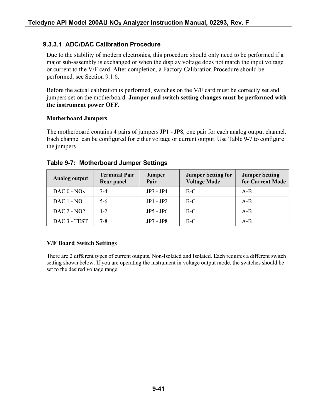
Motherboard Jumper Settings
3.1 ADC/DAC Calibration Procedure
Board Switch Settings
Motherboard Jumpers
Output or non-isolated current loop
V/F Board Switch Settings
Output or isolated current loop
Output
Page
V/F Board Settings
Temperature Amplifier Section
Status/Temp Board
Changing Output Voltage Ranges
Thermistor Temperature Amplifier Adjustments
Molybdenum Converter Thermocouple Amplifier Adjustments
Display Brownout
4.4 4-20 mA Current Output
Status Output Lines, External Contact Closures
Module Description
Power Supply Module Subassemblies
Power Supply Module Layout
Electrical Block Diagram
PSM Diagnostic Procedures
10 Power Supply Module LED Operation
Function Description
Ozone Generator
PermaPure Drier
11 Ozone Generator Control Conditions
Ozone Generator Subsystem
Flow/Pressure Sensor
Page
Flow/Pressure Sensor
NOx Sensor Module
10 NOx Sensor Module
8.1 PMT
NOx Sensor Module
Reaction Cell Temp
Preamp Board
11 PMT Cooler Subsystem
High Voltage P.S
PMT Cooler
12 High Voltage Power Supply
9 Z/S Valves
Sample Pump Diagnostic Procedures
Pneumatic System
Leak Check
Intentionally Blank
10 M200AU Spare Parts List
Teledyne API M200AU Spare Parts List
10-1
10-2
Teledyne API Model 200AU Expendable Kit
10-3
023180000 M200AU Expendables Kit Includes Qty
10-4
Appendix a Electrical Schematics
Table A-1 Electrical Schematics
Name
Table A-1 Electrical Schematics