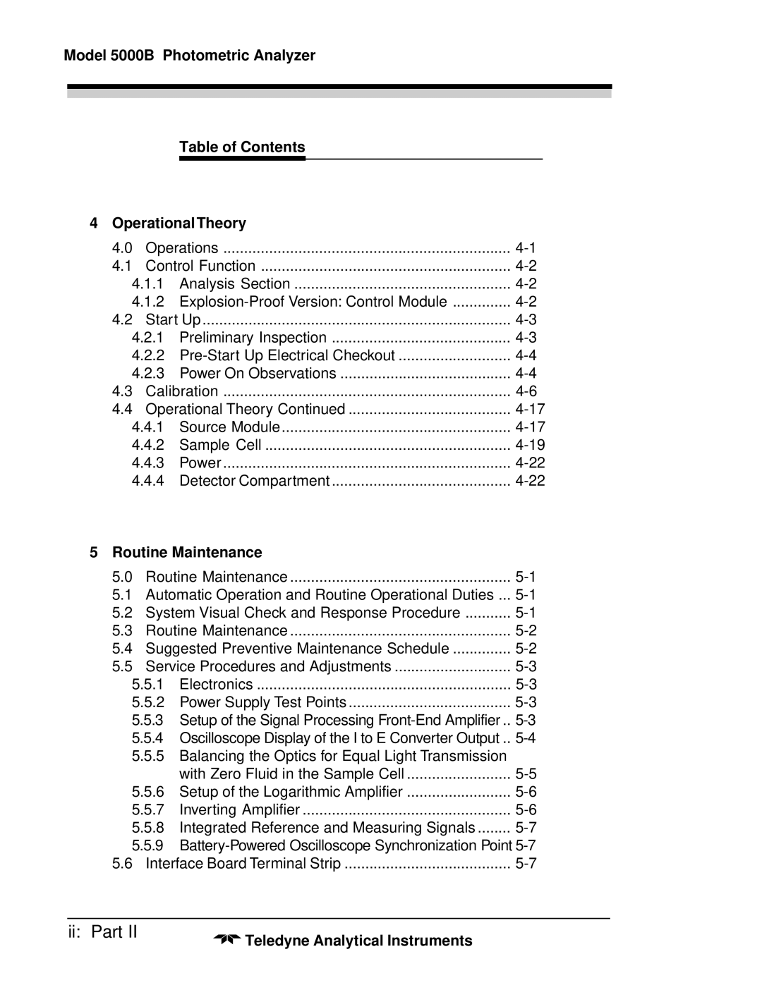
Model 5000B Photometric Analyzer
Table of Contents
4 OperationalTheory
4.0 | Operations | ||
4.1 | Control Function | ||
4.1.1 | Analysis Section | ||
4.1.2 | |||
4.2 | Start Up | ||
4.2.1 | Preliminary Inspection | ||
4.2.2 | |||
4.2.3 | Power On Observations | ||
4.3 | Calibration | ||
4.4 | Operational Theory Continued | ||
4.4.1 | Source Module | ||
4.4.2 | Sample Cell | ||
4.4.3 | Power | ||
4.4.4 | Detector Compartment | ||
5 Routine Maintenance |
| ||
5.0 | Routine Maintenance | ||
5.1 | Automatic Operation and Routine Operational Duties ... | ||
5.2 | System Visual Check and Response Procedure | ||
5.3 | Routine Maintenance | ||
5.4 | Suggested Preventive Maintenance Schedule | ||
5.5 | Service Procedures and Adjustments | ||
5.5.1 | Electronics | ||
5.5.2 | Power Supply Test Points | ||
5.5.3 Setup of the Signal Processing | |||
5.5.4 Oscilloscope Display of the I to E Converter Output .. | |||
5.5.5Balancing the Optics for Equal Light Transmission
| with Zero Fluid in the Sample Cell | |
5.5.6 Setup of the Logarithmic Amplifier | ||
5.5.7 | Inverting Amplifier | |
5.5.8 | Integrated Reference and Measuring Signals | |
5.5.9
5.6 Interface Board Terminal Strip |
ii: Part II | Teledyne Analytical Instruments |
|
