Operations/Analysis Unit 4
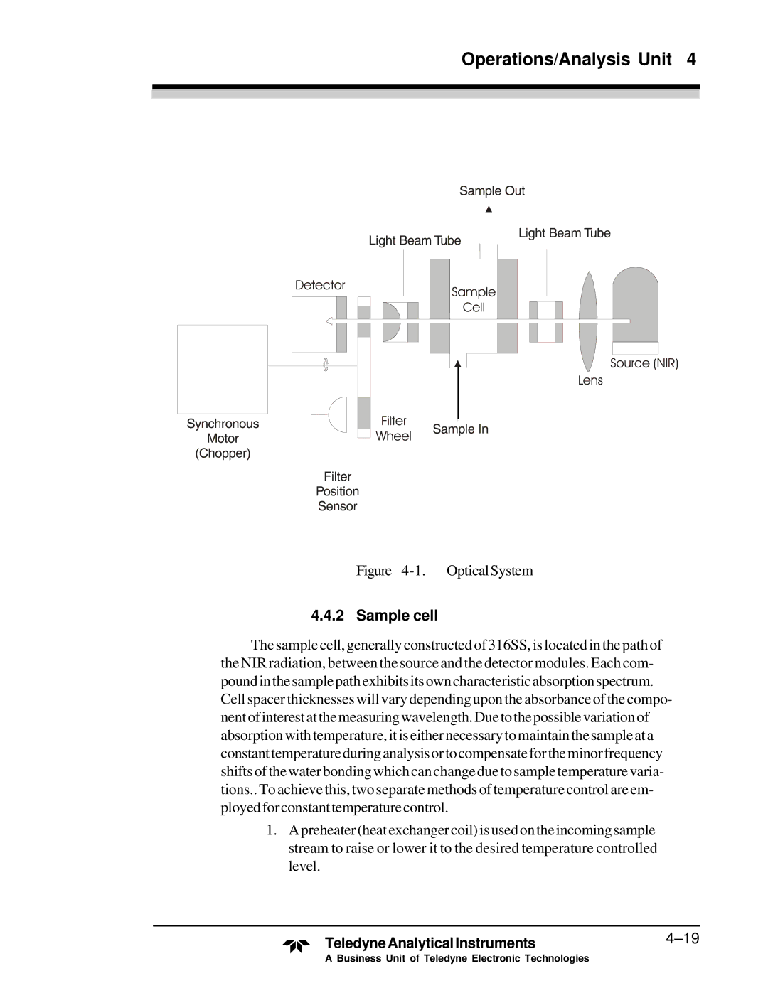
Figure 4-1. OpticalSystem
4.4.2 Sample cell
The sample cell, generally constructed of 316SS, is located in the path of the NIR radiation, between the source and the detector modules. Each com- poundinthesamplepathexhibitsitsowncharacteristicabsorptionspectrum. Cell spacer thicknesses will vary depending upon the absorbance of the compo- nentofinterestatthemeasuringwavelength.Duetothepossiblevariationof absorption with temperature, it is either necessary to maintain the sample at a constanttemperatureduringanalysisortocompensatefortheminorfrequency shifts of the water bonding which can change due to sample temperature varia- tions.. To achieve this, two separate methods of temperature control are em- ployedforconstanttemperaturecontrol.
1.A preheater (heat exchanger coil) is used on the incoming sample stream to raise or lower it to the desired temperature controlled level.
TeledyneAnalyticalInstruments4–19
A Business Unit of Teledyne Electronic Technologies