Properly Installing the Programmer Hardware
2)Connect port A of the XDS to the PC by using the cable supplied with the XDS.
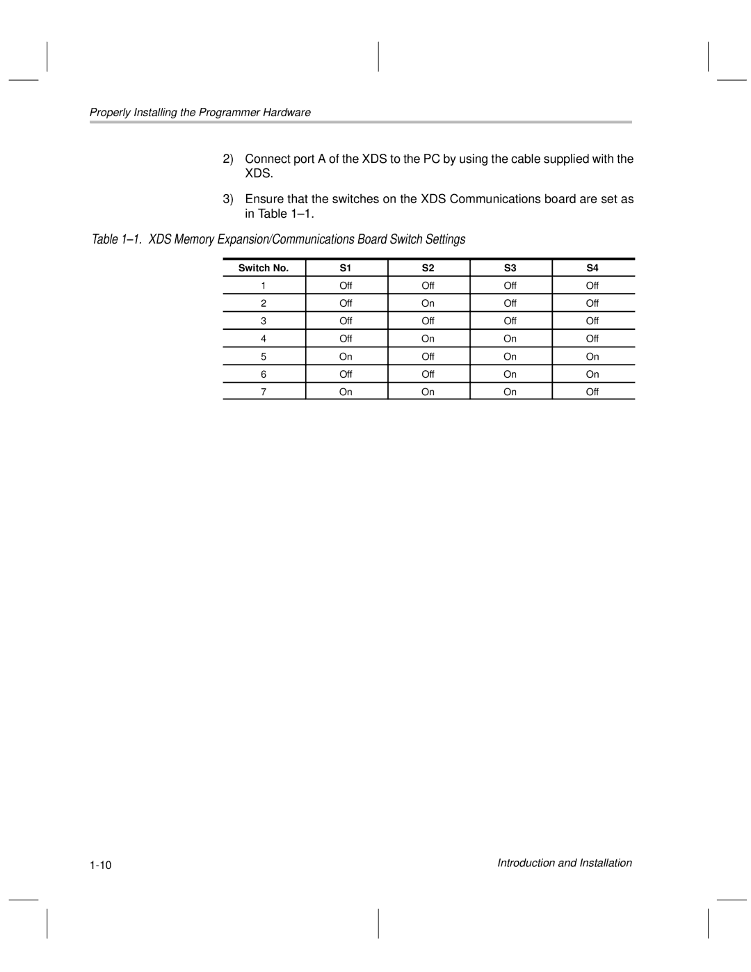
3)Ensure that the switches on the XDS Communications board are set as in Table 1±1.
Table 1±1. XDS Memory Expansion/Communications Board Switch Settings
Switch No. | S1 | S2 | S3 | S4 |
|
|
|
|
|
1 | Off | Off | Off | Off |
|
|
|
|
|
2 | Off | On | Off | Off |
|
|
|
|
|
3 | Off | Off | Off | Off |
|
|
|
|
|
4 | Off | On | On | Off |
|
|
|
|
|
5 | On | Off | On | On |
|
|
|
|
|
6 | Off | Off | On | On |
|
|
|
|
|
7 | On | On | On | Off |
Introduction and Installation |