Defining and Adding a Device to the Device Table
Valid types of memory are EPROM or EEPROM.
Legal VCC values are listed following the promptÐ0, 5, or 6. If you enter a value that is not one of the three valid choices, the following error message appears:
invalid VCC value: 0, 5, or 6 (hit any key)
Press any key to erase the error message and return to the prompt to enter the VCC value again.
Legal VPP values are listed following the promptÐ0, 5, 12, 12.5, or
21.If you enter a value which is not one of the five choices, the follow- ing error message appears:
invalid VPP value: 0, 5, 12, 12.5 or 21 (hit any key)
Press any key to erase the error message and return to the prompt to enter the VPP value again.
Valid pdt values fall in the decimal range of 0±127 as shown at the end of the prompt. If you enter a value that is out of the range, an error message is displayed as follows:
invalid Program Pulse Duration time: [0..127]
Press any key to erase the error message and return to the prompt to enter the Program Pulse Duration time again.
Step 4: Identify the secondary configuration parameters by answering the following four prompts:
Control Register:
This parameter is necessary only for programming TMS370 micro- controllers. The current valid values are 01Ah for the data EEPROM range and 1Ch for the program memory range.
Family Code:
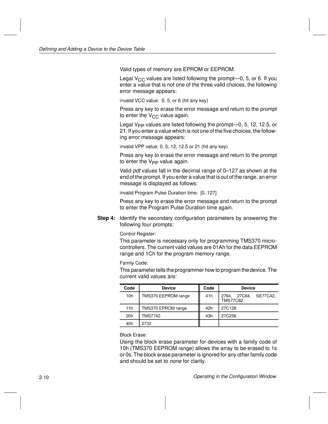
This parameter tells the programmer how to program the device. The current valid values are:
Code | Device | Code | Device |
|
|
|
|
10h | TMS370 EEPROM range | 41h | 2764, 27C64, SE77C42, |
|
|
| TMS77C82 |
11h | TMS370 EPROM range | 42h | 27C128 |
|
|
|
|
20h | TMS7742 | 43h | 27C256 |
|
|
|
|
40h | 2732 |
|
|
Block Erase:
Using the block erase parameter for devices with a family code of 10h (TMS370 EEPROM range) allows the array to be erased to 1s or 0s. The block erase parameter is ignored for any other family code and should be set to none for clarity.
Operating in the Configuration Window |