Display Window Overview and Description
3.5Display Window Overview and Description
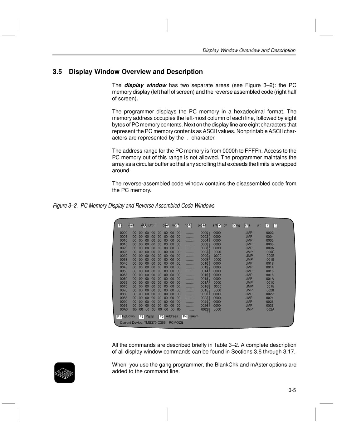
The display window has two separate areas (see Figure 3±2): the PC memory display (left half of screen) and the reverse assembled code (right half of screen).
The programmer displays the PC memory in a hexadecimal format. The memory address occupies the
The address range for the PC memory is from 0000h to FFFFh. Access to the PC memory out of this range is not allowed. The programmer maintains the array as a circular buffer so that any scrolling that exceeds the limits is wrapped around.
The
Figure 3±2. PC Memory Display and Reverse Assembled Code Windows
F ill L oad
O utputCOFF M ove P rogm S how
U pload
V erify E dit C onfig s Y s
Q uit
0000 | 00 | 00 | 00 | 00 | 00 | 00 | 00 | 00 | 0000 | 0000 | JMP | 0002 |
0008 | 00 | 00 | 00 | 00 | 00 | 00 | 00 | 00 | 0002 | 0000 | JMP | 0004 |
0010 | 00 | 00 | 00 | 00 | 00 | 00 | 00 | 00 | 0004 | 0000 | JMP | 0006 |
0018 | 00 | 00 | 00 | 00 | 00 | 00 | 00 | 00 | 0006 | 0000 | JMP | 0008 |
0020 | 00 | 00 | 00 | 00 | 00 | 00 | 00 | 00 | 0008 | 0000 | JMP | 000A |
0028 | 00 | 00 | 00 | 00 | 00 | 00 | 00 | 00 | 000A | 0000 | JMP | 000C |
0030 | 00 | 00 | 00 | 00 | 00 | 00 | 00 | 00 | 000C | 0000 | JMP | 000E |
0038 | 00 | 00 | 00 | 00 | 00 | 00 | 00 | 00 | 000E | 0000 | JMP | 0010 |
0040 | 00 | 00 | 00 | 00 | 00 | 00 | 00 | 00 | 0010 | 0000 | JMP | 0012 |
0048 | 00 | 00 | 00 | 00 | 00 | 00 | 00 | 00 | 0012 | 0000 | JMP | 0014 |
0050 | 00 | 00 | 00 | 00 | 00 | 00 | 00 | 00 | 0014 | 0000 | JMP | 0016 |
0058 | 00 | 00 | 00 | 00 | 00 | 00 | 00 | 00 | 0016 | 0000 | JMP | 0018 |
0060 | 00 | 00 | 00 | 00 | 00 | 00 | 00 | 00 | 0018 | 0000 | JMP | 001A |
0068 | 00 | 00 | 00 | 00 | 00 | 00 | 00 | 00 | 001A | 0000 | JMP | 001C |
0070 | 00 | 00 | 00 | 00 | 00 | 00 | 00 | 00 | 001C | 0000 | JMP | 001E |
0078 | 00 | 00 | 00 | 00 | 00 | 00 | 00 | 00 | 001E | 0000 | JMP | 0020 |
0080 | 00 | 00 | 00 | 00 | 00 | 00 | 00 | 00 | 0020 | 0000 | JMP | 0022 |
0088 | 00 | 00 | 00 | 00 | 00 | 00 | 00 | 00 | 0022 | 0000 | JMP | 0024 |
0090 | 00 | 00 | 00 | 00 | 00 | 00 | 00 | 00 | 0024 | 0000 | JMP | 0026 |
0098 | 00 | 00 | 00 | 00 | 00 | 00 | 00 | 00 | 0026 | 0000 | JMP | 0028 |
00A0 | 00 | 00 | 00 | 00 | 00 | 00 | 00 | 00 | 0028 | 0000 | JMP | 002A |
F1 PgDown
F2 PgUp
F3 Address
F4 DisAsm
Current Device: TMS370 C256 PCMODE
All the commands are described briefly in Table 3±2. A complete description of all display window commands can be found in Sections 3.6 through 3.17.
When you use the gang programmer, the BlankChk and mAster options are added to the command line.