APPENDIX 4 SYSTEM MODE
A4.7 Additional Information
A4.7.1 Self-Diagnostic Test Result Sample and Descriptions (Cont.)
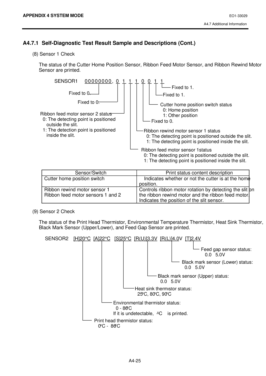
(8)Sensor 1 Check
The status of the Cutter Home Position Sensor, Ribbon Feed Motor Sensor, and Ribbon Rewind Motor Sensor are printed.
| SENSOR1 0 0 0 0 0 0 0 0 , 0 | 1 1 1 0 0 1 1 |
|
|
|
|
|
| ||||||||||||||||||||||||||
|
|
|
|
|
|
|
|
|
|
|
|
|
|
|
|
|
|
|
|
|
|
|
|
|
|
|
|
|
| Fixed to 1. | ||||
|
|
|
|
|
|
|
|
|
|
|
|
|
|
|
|
|
|
|
|
|
|
|
|
|
|
|
|
|
| |||||
|
|
|
|
|
|
|
|
|
|
|
|
|
|
|
|
|
|
|
|
|
|
|
|
|
|
|
|
|
|
|
|
|
|
|
|
| Fixed to 0. |
|
|
|
|
|
|
|
|
|
|
|
|
|
|
|
|
|
|
|
|
|
|
|
|
|
|
|
|
|
|
| |
|
|
|
|
|
|
|
|
|
|
|
|
|
|
|
|
|
|
|
|
|
|
| Fixed to 1. |
|
|
| ||||||||
|
|
|
|
|
|
|
|
|
|
|
|
|
|
|
|
|
|
|
|
|
|
|
|
|
|
|
| |||||||
|
|
|
|
|
|
|
|
|
|
|
|
|
|
|
|
|
|
|
|
|
|
|
|
|
|
|
|
|
| |||||
|
|
|
|
|
|
|
|
|
|
|
|
|
|
|
|
|
|
|
|
|
|
|
|
|
|
|
|
|
|
|
|
|
| |
|
|
|
|
|
|
|
|
|
|
|
|
|
|
|
|
|
|
|
|
|
|
|
|
|
|
|
|
|
|
|
|
|
|
|
|
|
| Fixed to 0. |
|
|
|
|
|
|
|
|
|
|
|
|
|
|
|
|
|
|
|
| Cutter home position switch status |
|
| ||||||||
|
|
|
|
|
|
|
|
|
|
|
|
|
|
|
|
|
|
|
|
|
|
| ||||||||||||
|
|
|
|
|
|
|
|
|
|
|
|
|
|
|
|
|
|
|
|
|
|
|
|
|
|
|
|
| ||||||
Ribbon feed motor sensor 2 status |
|
|
|
|
|
|
|
|
|
|
|
|
|
|
|
|
|
|
|
|
| 0: Home position |
|
| ||||||||||
|
|
|
|
|
|
|
|
|
|
|
|
|
|
|
|
|
|
|
|
| 1: Other position |
|
| |||||||||||
|
|
|
|
|
|
|
|
|
|
|
|
|
|
|
|
|
|
|
|
|
|
| ||||||||||||
| 0: The detecting point is positioned |
|
|
|
|
|
|
|
|
|
|
|
|
|
|
|
|
|
|
|
| |||||||||||||
|
|
|
|
|
|
|
|
|
|
|
|
|
|
|
|
|
|
|
|
|
|
|
|
|
| |||||||||
|
|
|
|
|
|
|
|
|
|
|
|
|
| Fixed |
| to 0. |
|
|
|
| ||||||||||||||
| outside the slit. |
|
|
|
|
|
|
|
|
|
|
|
|
|
|
|
|
| ||||||||||||||||
|
|
|
|
|
|
|
|
|
|
|
|
|
|
|
|
|
|
|
|
|
|
|
|
|
| |||||||||
|
|
|
|
|
|
|
|
|
|
|
|
|
|
|
|
|
|
|
|
|
|
|
|
|
| |||||||||
| 1: The detection point is positioned |
|
|
|
|
|
|
|
|
| Ribbon rewind motor sensor 1 status | |||||||||||||||||||||||
|
|
|
|
|
|
|
|
|
| |||||||||||||||||||||||||
| inside the slit. |
|
|
|
|
|
|
|
|
| 0: The detecting point is positioned outside the slit. | |||||||||||||||||||||||
|
|
|
|
|
|
|
|
|
|
|
|
|
|
|
|
|
|
| 1: The detecting point is positioned inside the slit. | |||||||||||||||
|
|
|
|
|
|
|
|
|
|
|
|
|
|
|
|
|
|
|
|
| ||||||||||||||
|
|
|
|
|
|
|
|
|
|
|
|
|
|
|
|
|
| Ribbon feed motor sensor 1status |
| |||||||||||||||
|
|
|
|
|
|
|
|
|
|
|
|
|
|
|
|
| ||||||||||||||||||
|
|
|
|
|
|
|
|
|
|
|
|
|
|
|
|
|
|
| 0: The detecting point is positioned outside the slit. |
| ||||||||||||||
|
|
|
|
|
|
|
|
|
|
|
|
|
|
|
|
|
|
| 1: The detecting point is positioned inside the slit. |
| ||||||||||||||
|
|
|
|
|
|
|
|
|
|
|
|
|
|
|
|
|
|
|
|
|
|
|
|
|
|
|
|
|
|
|
|
|
| |
|
|
|
|
|
|
|
|
|
|
|
|
|
|
|
|
|
|
|
|
|
|
|
|
|
|
|
|
|
|
|
|
|
|
|
|
|
| Sensor/Switch |
|
|
|
|
|
|
|
|
|
|
|
|
|
|
|
|
|
| Print status content description | ||||||||||||
| Cutter home position switch |
|
|
|
|
|
|
| Indicates whether or not the cutter is at the home | |||||||||||||||||||||||||
|
|
|
|
|
|
|
|
|
|
|
|
|
|
|
|
| position. | |||||||||||||||||
| Ribbon rewind motor sensor 1 |
|
|
|
|
|
|
| Controls ribbon motor rotation by detecting the slit on | |||||||||||||||||||||||||
| Ribbon feed motor sensors 1 and 2 |
|
|
|
|
|
|
| the ribbon rewind motor and the ribbon feed motor. | |||||||||||||||||||||||||
|
|
|
|
|
|
|
|
|
|
|
|
|
|
|
|
| Indicates the position of the slit sensor. | |||||||||||||||||
(9)Sensor 2 Check
The status of the Print Head Thermistor, Environmental Temperature Thermistor, Heat Sink Thermistor, Black Mark Sensor (Upper/Lower), and Feed Gap Sensor are printed.
SENSOR2 [H]20°C [A]22°C [S]25°C [R(U)]3.3V [R(L)]4.0V [T]2.4V
![]() Feed gap sensor status: 0.0 – 5.0V
Feed gap sensor status: 0.0 – 5.0V
Black mark sensor (Lower) status: 0.0 – 5.0V
Black mark sensor (Upper) status: 0.0 – 5.0V
Heat sink thermistor status: 25°C, 80°C, 90°C
Environmental thermistor status: 0 - 86°C
If it is undetectable,
Print head thermistor status: 0°C - 86°C