APPENDIX 4 SYSTEM MODE
A4.7 Additional Information
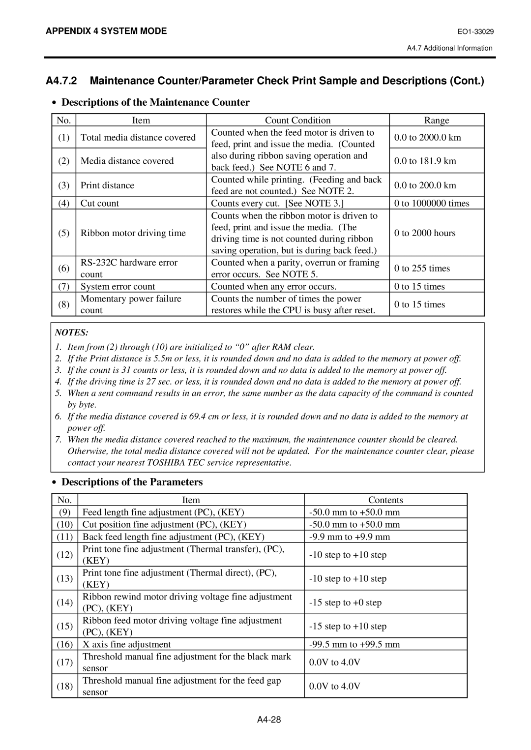
A4.7.2 Maintenance Counter/Parameter Check Print Sample and Descriptions (Cont.)
∙Descriptions of the Maintenance Counter
No. | Item | Count Condition | Range | |
(1) | Total media distance covered | Counted when the feed motor is driven to | 0.0 to 2000.0 km | |
feed, print and issue the media. (Counted | ||||
|
|
| ||
(2) | Media distance covered | also during ribbon saving operation and | 0.0 to 181.9 km | |
back feed.) See NOTE 6 and 7. | ||||
|
|
| ||
(3) | Print distance | Counted while printing. (Feeding and back | 0.0 to 200.0 km | |
feed are not counted.) See NOTE 2. | ||||
|
|
| ||
(4) | Cut count | Counts every cut. [See NOTE 3.] | 0 to 1000000 times | |
|
| Counts when the ribbon motor is driven to |
| |
(5) | Ribbon motor driving time | feed, print and issue the media. (The | 0 to 2000 hours | |
driving time is not counted during ribbon | ||||
|
|
| ||
|
| saving operation, but is during back feed.) |
| |
(6) | Counted when a parity, overrun or framing | 0 to 255 times | ||
count | error occurs. See NOTE 5. | |||
|
| |||
(7) | System error count | Counted when any error occurs. | 0 to 15 times | |
(8) | Momentary power failure | Counts the number of times the power | 0 to 15 times | |
count | restores while the CPU is busy after reset. | |||
|
|
NOTES:
1.Item from (2) through (10) are initialized to “0” after RAM clear.
2.If the Print distance is 5.5m or less, it is rounded down and no data is added to the memory at power off.
3.If the count is 31 counts or less, it is rounded down and no data is added to the memory at power off.
4.If the driving time is 27 sec. or less, it is rounded down and no data is added to the memory at power off.
5.When a sent command results in an error, the same number as the data capacity of the command is counted by byte.
6.If the media distance covered is 69.4 cm or less, it is rounded down and no data is added to the memory at power off.
7.When the media distance covered reached to the maximum, the maintenance counter should be cleared. Otherwise, the total media distance covered will not be updated. For the maintenance counter clear, please contact your nearest TOSHIBA TEC service representative.
∙Descriptions of the Parameters
No. | Item | Contents | |
(9) | Feed length fine adjustment (PC), (KEY) | ||
(10) | Cut position fine adjustment (PC), (KEY) | ||
(11) | Back feed length fine adjustment (PC), (KEY) | ||
(12) | Print tone fine adjustment (Thermal transfer), (PC), | ||
(KEY) | |||
|
| ||
(13) | Print tone fine adjustment (Thermal direct), (PC), | ||
(KEY) | |||
|
| ||
(14) | Ribbon rewind motor driving voltage fine adjustment | ||
(PC), (KEY) | |||
|
| ||
(15) | Ribbon feed motor driving voltage fine adjustment | ||
(PC), (KEY) | |||
|
| ||
(16) | X axis fine adjustment | ||
(17) | Threshold manual fine adjustment for the black mark | 0.0V to 4.0V | |
sensor | |||
|
| ||
(18) | Threshold manual fine adjustment for the feed gap | 0.0V to 4.0V | |
sensor | |||
|
|