B-EX4T1 SERIES
TOSHIBA Barcode Printer
CE Compliance for EU only
N258
IP20
VORSICHT
Owners Manual
Waste Recycling information for users
For USA
For safety
For Europe
For Canada
Safety Summary
Meanings of Each Symbol
and cause fire or electric shock
Precautions
Request Regarding Maintenance
Fire or electric shock could
PRINTER SETUP
TABLE OF CONTENTS
PRODUCT OVERVIEW
ON LINE MODE
1.1 Introduction
1.2 Features
1. PRODUCT OVERVIEW
1.3 Unpacking
… Power cord
1.4 Accessories
ENGLISH VERSION EO1-33089 1.4 Accessories
1.5.1
Dimensions
Appearance
1.5.2 Front View
1.5.4 Operation Panel
1.5.5 Interior
Type
1.6 Options
Option Name
Description
Procedure
2. PRINTER SETUP
Setup Flow
Reference
2.1 Installation
2.2 Connecting the Power Cord
Example of US Type
2.3 Loading Supplies
ENGLISH VERSION EO1-33089 2.3 Loading Supplies
2.3.1 Loading the Media
2.3.1 Loading the Media Cont
Setting the Feed Gap Sensor position
Setting the Black Mark Sensor position
STANDARD/PEEL OFF position
14. Loading with cutter
2.3.2 Loading the Ribbon
Ribbon path
2.3.2 Loading the Ribbon Cont
Auto Ribbon Saving Mode
2.4 Connecting the Cables to Your Printer
2.5 Turning the Printer ON/OFF
2.5.1 Turning ON the Printer
ONLINE Mode
2.6 Printer Setting
Power OFF
PAUSE state
Function
Cont
2.6.1 User System Mode
9LOG ⇒ Section
Menu
2.6.2 Parameter Setting
Contents of the Parameter Set Menu
Sub menu
Cont
2.6.2.1 Printer Set
2.6.2 Parameter Setting Cont
2.6.2.2 Software Set
This parameter is to choose the function of the FEED key
This parameter is to choose a Maxicode specification
18 ENERGY TYPE
16 XML
17 THRESHOLD SELECT
19 PW SAVE TIME
2.6.2.3 PANEL
2.6.4 Basic Program Setting
2.6.2 Parameter Setting Cont 2.6.3 Enabling LAN/WLAN
2.6.2.4 PASSWORD
4 EXPAND MODE
2.6.4 Basic Program Setting Cont 2.6.5 Enabling Z-Mode
3 TRACE
1 Z-MODE
2.6.6 Automatic Calibration
1 AUTO CALIB
1 BUFFER
2.6.7 Dump Mode Setting
2 DUMP LIST
Receive Buffer Size
2.6.7 Dump Mode Setting Cont
The data in the receive buffer is printed as follows
Required Media Length
The Log menu allows saving print logs in a USB memory
2.6.8 Logging
1 LOG
The System Mode consists of the following menus
2.6.9 System Mode
11RTC ⇒ Section
2.6.10 Interface Setting
Contents of the Interface Menu
6 SUBNET MASK
3 BASIC INFORMATION
5 GATEWAY ADDRESS
7 SOCKET PORT
10 DHCP CLIENT ID
8 PORT NUMBER
9 DHCP
11 DHCP HOST NAME
2.6.10 Interface Setting Cont
13 WLAN MODE
16 802.11b BAUD
14 DEFAULT KEY
15 802.11b CHANNEL
17 802.11g CHANNEL
21 WINS ADDRESS
19 WLAN POWER SAVE
20 WINS
1 USB SERIAL ID
4 PARITY
2 DATA LENGTH
3 STOP BIT
5 CONTROL
This parameter is to set date and time
2.6.12 Copying Data to/from USB Memory
2.7.1 Introduction
2.7 Installing the Printer Drivers
2.7.3 Installing the Printer Driver
2.7.2 General Description
2.7.4 Preparation for Installation
5 When the installation is completed, click the Finish button
E2-42
2.7.5 Installation under Windows 2000/XP/Server2003
6 Specify a printer port and click the Next button
9 The list of the installable printer is displayed
E2-46
17 Installation of the printer driver starts
2.7.6 Installation under Windows Vista/Server2008/7/Server2008R2
E2-48
E2-49
11 Installation starts
2.7.7 Installation under Windows 2000 USB with Plug & Play Enabled
E2-51
9 When the screen on the right is displayed, click the Yes button
E2-53
E2-54
2.7.10 Uninstalling the Printer Driver
4 Click the Finish button to start to delete the printer drivers
2 To delete the V6.5 Build75 or V6.5 Build77
z Deleting the setup information configured during the preparation
E2-57
2.8 Print Test
Adjustment
2.8 Print Test Cont
„ When using a Strip Module or an optional Cutter Module
Fine adjustment ⇒Section
2.9 Position and Print Tone Fine Adjustment
2.9.1 Fine Adjustment
Contents of the Fine Adjustment Menu
2.9.1 Fine AdjustmentCont
2 CUT ADJ
Example of Cut Position Fine Adjustment
Example of Peel-off Position Fine Adjustment
E2-62
Example of Reverse Feed Amount Fine Adjustment
3 BACK ADJ
Example of X Coordinate Fine Adjustment
4 X ADJUST
E2-64
Print tone for the thermal transfer printing is fine adjusted
8 RBN ADJ.BK
2.9.1 Fine Adjustment Cont
10 THRESHOLD TRANS
9 THRESHOLD REFL
2.10 Threshold Setting
5 Press the RIGHT to see the details
2.10 Threshold Setting Cont
7 The result after manually setting the threshold is displayed
e.g Succeeded
Sensor adjustment
2.11 Sensor Setting
Contents of the Sensor Adjust Menu
2.11 Sensor Setting Cont
3 PE REFL./TRANS
ON LINE MODE
Key Functions
Error state
3.2 LCD
Online state
3.3 Operation Example
„ Online Mode
3.3 Operation Example Cont
„ Help Guide Message
„ Cancellation of Print Job
4.1 Cleaning
4. MAINTENANCE
4.1.1 Print Head/Platen/ Sensors
4.1.1 Print Head/Platen/ Sensors Cont
4.1.2 Covers and Panels
4.1.3 Optional Cutter Module
5. TROUBLESHOOTING
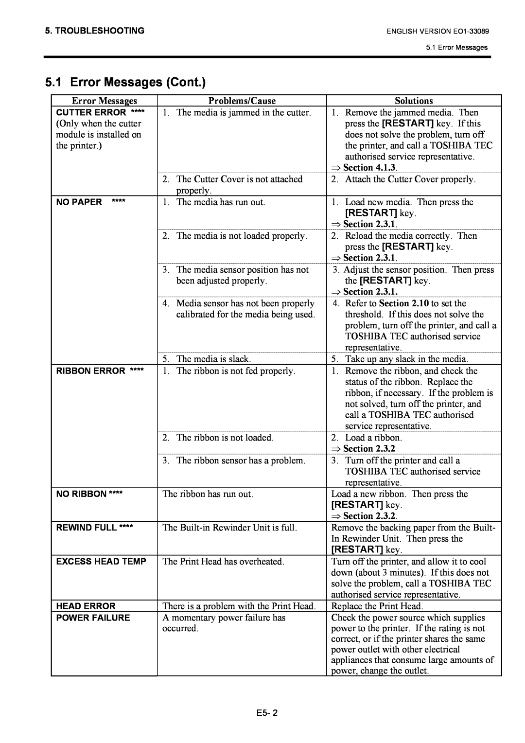
5.1 Error Messages
5.1 Error Messages Cont
Problems/Cause
5.2 Possible Problems
ENGLISH VERSION EO1-33089 5.2 Possible Problems
5.3 Removing Jammed Media
ENGLISH VERSION EO1-33089 5.3 Removing Jammed Media
Model
6. PRINTER SPECIFICATIONS
This section describes the printer specifications
B-EX4T-GS12-QM-R/CN-R
Bar code types
7.1 Media
7. SUPPLY SPECIFICATIONS
7.1.1 Media Type
B-EX4T-TS12-QM-R
Label
7.1.2 Detection Area of the Transmissive Sensor
Tag paper with square holes
7.1.3 Detection Area of the Reflective Sensor
7.1.4 Effective Print Area
7.1.5 RFID Tags
Cautions for using RFID Tags
7 Printing on Bump Chip/Antenna Area
7.3 Recommended Media and Ribbon Types
7.2 Ribbon
ENGLISH VERSION EO1-33089 7.2 Ribbon
7.4 Care/Handling of Media and Ribbon
7.3 Recommended Media and Ribbon Types Cont
Combination of Media and Ribbon
APPENDIX 1 MESSAGES AND LEDS
Symbols in the message
Page
Example ESCT20G30LF NUL Command error
Example ESCPC0010A00,0300,2,2,A,00,BLFNUL Command error
Example
USB interface Standard
APPENDIX 2 INTERFACE
LAN Standard
Serial interface Option B-EX700-RS-QM-R
Parallel interface Centronics Option B-EX700-CEN-QM-R
IEEE1284-B Connector
USB Host interface Option B-EX700-RTC-QM-R
Wireless LAN Option B-EX700-WLAN-QM-R
Shared key for WEP, PSK, PEAP, TLS, TTLS, MD5, LEAP, EAP-FAST
Expansion I/O Interface Option B-EX700-IO-QM-R
N.C. No Connection
B-EX700-RFID-U2-EU-R
RFID Option
B-EX700-RFID-U2-US-R
B-EX700-RFID-H1-QM-R
APPENDIX 3 PRINT SAMPLES
APPENDIX 3 PRINT SAMPLES
Font
ENGLISH VERSION EO1-33089 APPENDIX 3 PRINT SAMPLES
APPENDIX 3 PRINT SAMPLES Cont
Bar codes
UPC-A+5 digits
UPC-A
GS1 DataBar Stacked
GS1 DataBar Limited
EAN-13
EAN-8
GS1 DataBar Expanded Stacked
UCC/EAN-128 with CC-A or CC-B
APPENDIX 4 GLOSSARIES
Printer IP address
EO1-33089