SX8T Series
Vorsicht
CE Compliance for EU only
SX8T Series
Waste Recycling information for users
For all countries and areas
Meanings of Each Symbol
Safety Summary
Request Regarding Maintenance
Precautions
Table of Contents
EA4-1
EA1-1
EA2-1
EA3-1
Product Overview
Introduction Features
Accessories
Supply Holder Frame L
Wing Bolt 2 pcs
Rear View
Dimensions
Appearance
Front View
Interior
Operation Panel
Option Name Type Usage
Options
Manual threshold setting
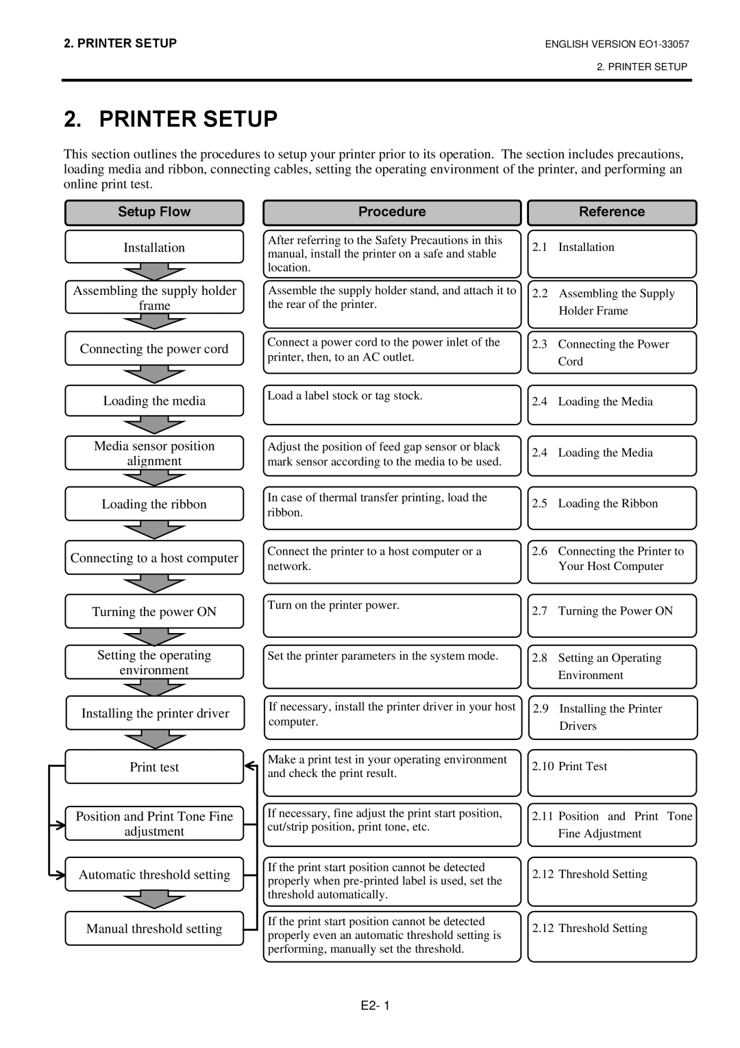
Printer Setup
Setup Flow
Procedure
Assembling the Supply Holder Frame
Installation
Example of US Type
Connecting the Power Cord
Loading the Media
Open the Top Cover and the Right Side Cover
Set the Head Lever to the Open position
Bush Notch
Fixed sensor Movable sensor
Detail of Movable Sensor
Detail of Fixed Sensor
Feed Gap Sensor position adjustment
Black Mark Sensor position adjustment
Close the Top Cover and Right Side Cover
Batch mode
Strip mode Option
Cut mode Option
Tag paper or Thick paper
Label or Thin media
Loading the Ribbon
Loading the Ribbon
Close the Head Lock Plate, Right Side Cover, and Top Cover
Connecting the Printer to Your Host Computer
Turning the Printer
How to enter the System Mode
Sequentially
Parameter Setting
While 2PARAMETER SET is displayed on the LCD Message
Time the Pause key is pressed, the sub menus are displayed
After selecting a character code, press the Pause key
Character Zero Selection
Character Code Selection
Use the Feed or Restart key to select a desired option
After selecting a data length, press the Pause key
Baud Rate Selection
After selecting a baud rate, press the Pause key
Data Length Selection
Stop Bit Length Selection
Parity Selection
Flow Control Code Selection
After selecting an auto forward wait, press the Pause key
LCD Language Selection
After selecting a language, press the Pause key
Auto Forward Wait Selection
Head Up Cut Selection
Control Code Selection
Ribbon Save Function Selection
After selecting a ribbon type, press the Pause key
Ribbon Type Selection
After selecting the Feed key function, press the Pause key
Strip Wait Status Selection
After selecting the Strip Wait Status, press the Pause key
Feed Key Function Selection
After selecting a Euro code, press the Pause key
Kanji Code Selection
After selecting a Kanji code, press the Pause key
Euro Code Selection
After selecting an ACK/BUSY timing, press the Pause key
Auto Print Head Check Selection
After selecting auto print head check, press the Pause key
Centronics Interface ACK/BUSY Timing Selection
Web Printer Function Selection
Media Sensor Selection
After selecting the media sensor type, press the Pause key
Input Prime Selection
After selecting the Input Prime, press the Pause key
Expansion I/O Interface Type Selection
Plug & Play Selection
After selecting a Plug & Play, press the Pause key
Label End/Ribbon End Selection
After selecting the Back Feed Speed, press the Pause key
Pre-Strip Selection
This parameter is fixed to OFF Press the Pause key
Reverse Feed Speed Selection
Stabilizer Function Selection
Maxi Code Specification Selection
Strip Motor Torque Selection
This parameter is fixed to R0 Press the Pause key
After selecting a printing method, press the Pause key
Dump Mode Setting
After selecting the receive buffer, press the Pause key
Use the Feed or Restart key to select a printing method
Data in the receive buffer is printed as follows
Receive Buffer Size
Required Label Length
When the Pause key is pressed, Basic program is executed
While 6AUTO Calib is displayed on the LCD Message Display
Press the Pause key to enter the Automatic Calibration Mode
When 6AUTO Calib appears, press the Pause key
Automatic Calibration
LAN Setting
Time Setting
Date Setting
Real Time Clock Setting 3 Low Battery Check Setting
RTC Data Renewal Timing Setting
Cont
IP Address Setting TCP/IP
Feed and Pause keys
This parameter is to set a Gateway IP address
Printer IP Address
This parameter is to set an IP address
Gateway IP Address
Subnet Mask
This parameter is to set a Subnet Mask
Socket Port
This parameter is to enable Dhcp
Dhcp Client ID
This parameter is to set a Dhcp client ID
Dhcp Host Name
This parameter is to set a Dhcp host name
Ascii code and Hex. code correspondence table
Installing the Printer Drivers
Introduction
General Description
Parallel Interface
Installing the Printer Driver
Windows 98/Me
E2-52
Windows 2000/XP
E2-54
USB Interface
E2-56
E2-57
E2-58
Finish button
E2-60
E2-61
E2-62
Uninstalling the Printer Driver
Adding a LAN Port Windows 98/ME
Adding/Deleting a LAN Port
Deleting a LAN Port
Others
Printer Driver Upgrades
Using the Printer Driver
Print Test
Adjustment
When using an optional Cutter Module or Strip Module
Coordinate Fine Adjustment
Position and Print Tone Fine Adjustment
Feed Amount Fine Adjustment
Cut/Strip Position Fine Adjustment
When setting +0.0 mm
Position and Print
Tone Fine
Example of Cut Position Fine Adjustment
Example of Strip Position Fine Adjustment
Restart Feed
When setting +50.0 mm
When setting -50.0 mm
Position and Print Tone Fine Adjustment
Ribbon Motor Voltage Fine Adjustment
Manually set
Threshold Setting
Jam errors
Select the sensor to be adjusted by using the Feed key
Ribbon End Sensor Adjustment
Black Mark Sensor Adjustment
Feed Gap Sensor Adjustment
Black Mark Sensor/Feed Gap Sensor Adjustment No media
„ When using the Feed Gap Sensor
„ When using the Black Mark Sensor
„ Manual Threshold Setting
„ Storing a No Media Level Voltage
Press and hold the Restart or Feed key for about 3 seconds
THRESHOLDR4.0V THRESHOLDT4.0V THRESHOLDR3.9V
Operation Panel
On Line Operation
Reset
Operation
Press and hold the Restart key for 3 seconds or longer
Print Head/Platen
Maintenance
Cleaning
When the Cutter Module is fitted
Print Head/Platen Pinch Roller
Take out the Pinch Roller Ass’y from the printer
Attach the Ribbon End Sensor Plate to the printer
Plate with the Positioning Pins of the printer
Re-install the Media Guides using the screws
Covers and Panels
Optional Cutter Module
Remove the White Screw to detach the Media Guide
Remove jammed media, if any
Cutter Blade
Care must be taken not to pinch your fingers or hands
Troubleshooting
Error Messages
Restart key
Error Messages Problems/Cause
Possible Problems Causes Solutions
Possible Problems
Ribbon is not loaded properly Load the ribbon properly
Cutter blade is dirty Clean the cutter blade
Do not use any tool that may damage the Print Head
Removing Jammed Media
Removing Jammed Media
Printer Specifications
This section describes the printer specifications
Model
SX8T-TS12-QM-R
Label
Supply Specifications
Media
Media Type
Detection Area of the Transmissive Sensor
Label
Tag paper with square holes
Effective Print Area
Detection Area of the Reflective Sensor
Ribbon
Recommended Media and Ribbon Types
Media type Description
Ribbon type Description
Care/Handling of Media and Ribbon
Ribbon type
Combination of Media and Ribbon
Appendix 1 Messages and Leds
Symbols in the message
Printer did not succeed in writing data
When the Dhcp function is enabled
Base LAN Board is being initialised
Dhcp client is being initialized
Following message appears
Receive buffer 1M byte
Appendix 2 Interface
PIN
Connector
LED status Link LED
Number of ports Power source Self power Connector Type B
Number of ports Connector RJ-45
Standard
SX708-RFID-U2-EU-R
Serial interface Option B-SA704-RS-QM-R
Wireless LAN Option B-SA704-WLAN-QM-R
Expansion I/O Interface Option B-SA704-IO-QM-R
Appendix 3 Power Cord
When purchasing the power cord
At least, 125% of the rated current of the product
Appendix 4 Print Samples
Appendix 4 Print Samples
EAN13+5 digits
Interleaved 2
JAN13, EAN13
EAN13+2 digits
KIX Code
UPC-A+5 digits
Industrial 2
Customer bar code
Expansion I/O Interface
Appendix 5 Glossaries
Device used to remove labels from the backing paper
Media and ribbon
USB Universal Serial Bus
Power switch 2-3 Pre-printed media 78, A5-1 Print head 1-4
Index
A3-1
Index
EO1-33057D