Optional Devices
3.Turn the computer upside down and remove the battery pack (refer to Replacing the battery pack section in Chapter 6, Power, if required).
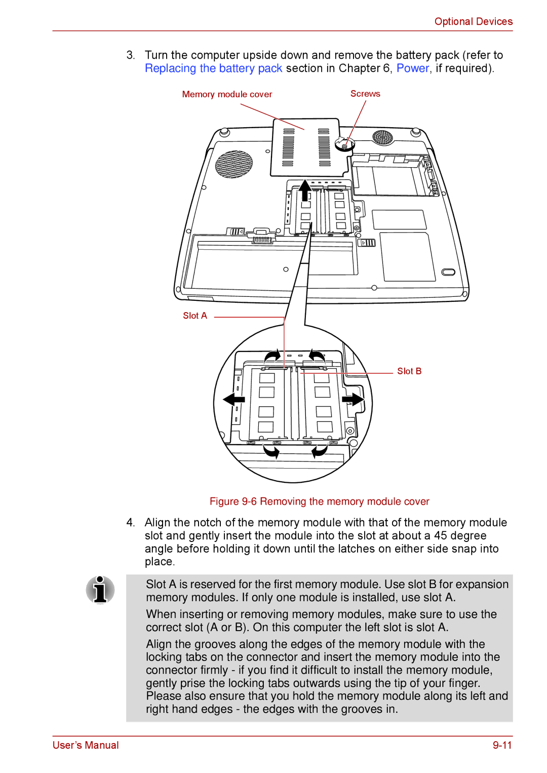
Memory module cover | Screws |
Slot A
Slot B
Figure 9-6 Removing the memory module cover
4.Align the notch of the memory module with that of the memory module slot and gently insert the module into the slot at about a 45 degree angle before holding it down until the latches on either side snap into place.
■Slot A is reserved for the first memory module. Use slot B for expansion memory modules. If only one module is installed, use slot A.
■When inserting or removing memory modules, make sure to use the correct slot (A or B). On this computer the left slot is slot A.
■Align the grooves along the edges of the memory module with the locking tabs on the connector and insert the memory module into the connector firmly - if you find it difficult to install the memory module, gently prise the locking tabs outwards using the tip of your finger. Please also ensure that you hold the memory module along its left and right hand edges - the edges with the grooves in.
User’s Manual |