Chapter 4 Replacement Procedures
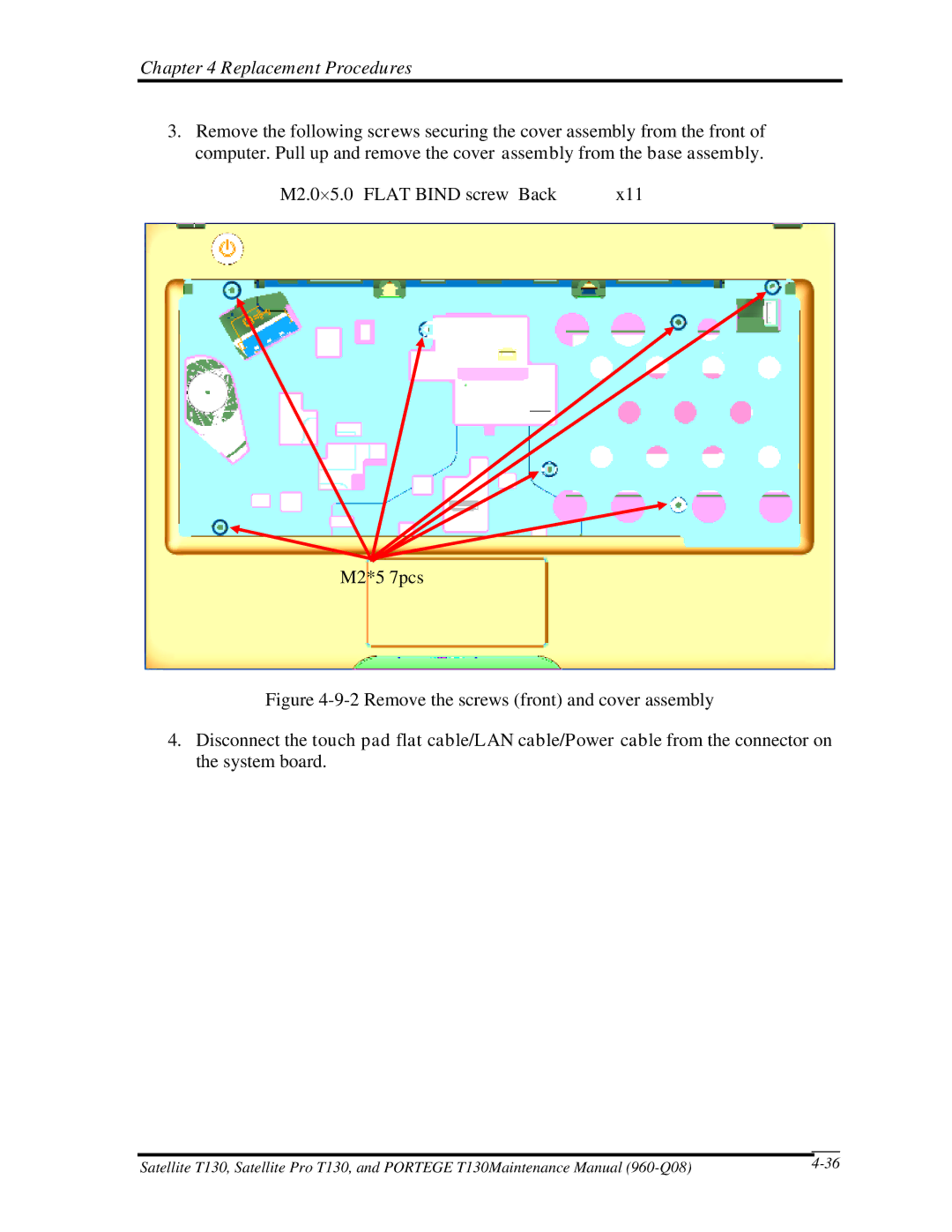
3.Remove the following screws securing the cover assembly from the front of computer. Pull up and remove the cover assembly from the base assembly.
M2.0×5.0 FLAT BIND screw Back | x11 |
M2*5 7pcs
Figure 4-9-2 Remove the screws (front) and cover assembly
4.Disconnect the touch pad flat cable/LAN cable/Power cable from the connector on the system board.
|
|
Satellite T130, Satellite Pro T130, and PORTEGE T130Maintenance Manual |