Board Layout
Appendix B Board Layout
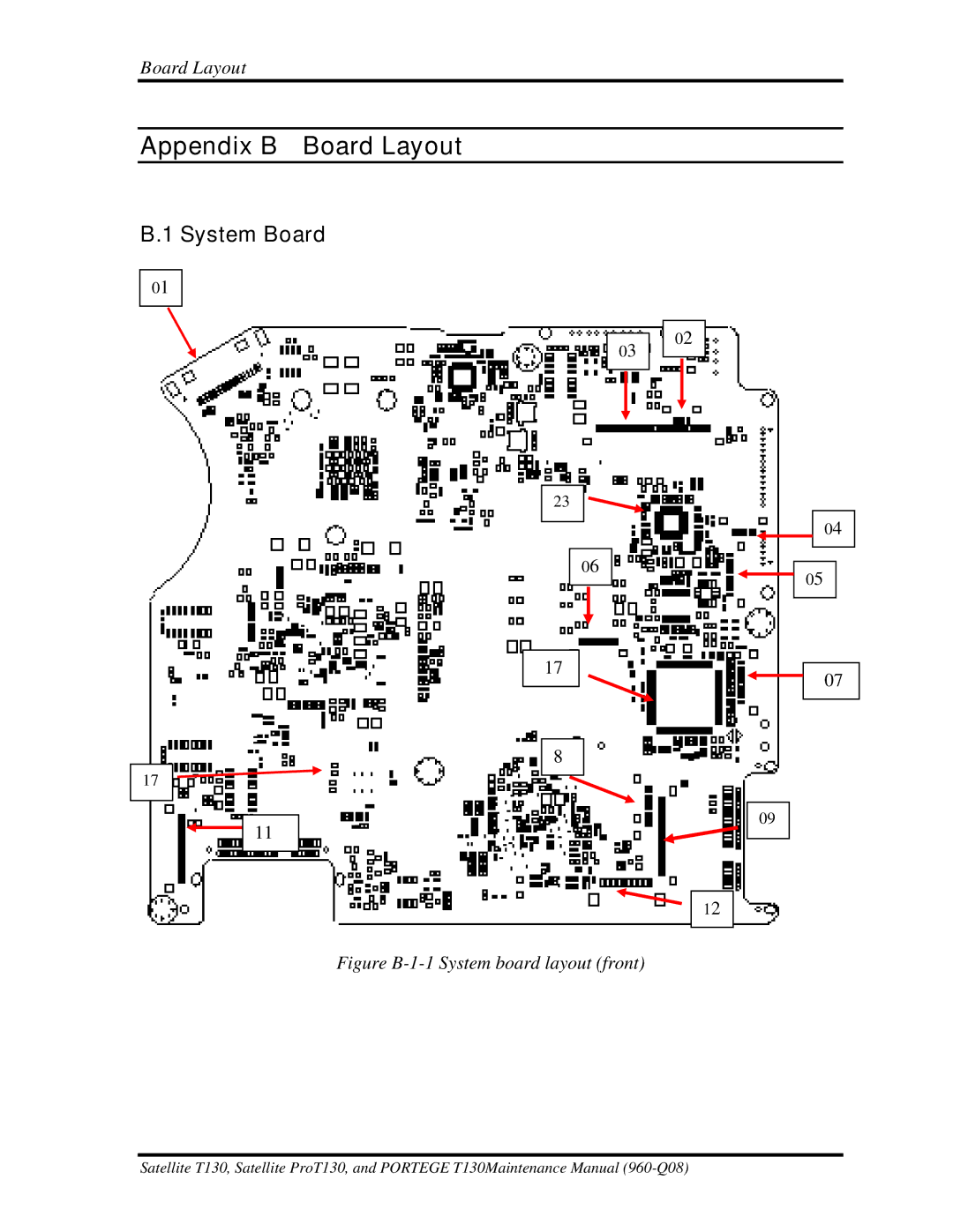
B.1 System Board
01
03
23
06
02
04
05
17![]()
![]()
![]() 11
11
17
8
09
12
Figure B-1-1 System board layout (front)
07
Satellite T130, Satellite ProT130, and PORTEGE T130Maintenance Manual
Board Layout
01
03
23
06
02
04
05
17![]()
![]()
![]() 11
11
17
8
09
12
07
Satellite T130, Satellite ProT130, and PORTEGE T130Maintenance Manual