Split Type
Contents
Original instruction
Indication Explanation
Explanation of indications
Explanation of illustrated marks
Work undertaken Protective gear worn
Description
Confirmation of warning label on the main unit
Precaution for Safety
Proceeding with the repair work
Refrigerant used by this air conditioner is the R410A
Resistance and water drainage
Relocation
Specifications
Model Sound power level dB Weight kg Cooling Heating
Explanations given to user
Flare nut
Safety Caution Concerned to New Refrigerant
Pipe Materials
Copper pipe Piping
Used tool Usage
Tools
General tools Conventional tools can be used
R410A Conventional air
Model Indoor unit
Concealed Duct High static pressure Type
RAV-SM2242DT-TR RAV-SM2802DT-TR
Concealed Duct High static pressure Type Contined
SM2242DT-E
Indoor Unit
Indoor unit
Dimension table
Unit
Indoor
100
RAV-SM2242 type
350 300 250 200 150 100 3200 3360
RAV-SM2802 type
High static pressure F3
Wire connection change of fan motor
Low static pressure F1
Standard Middle static pressure F2
Parts name Type Specifications
Specifications of Electrical Parts
Outdoor unit
Indoor Controller Block Diagram
Connection of Wired Simple Remote Controller
Indoor unit #1 Header
Outline of specifications Remarks
Control outline
Outside temp Correction value a
Indoor formation
Setup data
Ta ˚C Cooling +1.5
Tc, Tcj
Tcn
Conditions Tc n
Control temp. C
Setup at shipment
Heat
Case of wired remote controller
Usual control
MCC-1403
Print Circuit Board
Function Connector Pin Specifications Remarks
Optional Connector Specifications of Indoor P.C. Board
Before troubleshooting
Troubleshooting procedure
Wired remote controller type
Procedure
Main remote controller RBC-AMT32E
Confirmation of error log
How to read check monitor display
Remote controller switch monitoring function
Check Code List Indoor Indoor unit detected
Remote controller detected
Central control devices detected
Error mode detected by indoor unit
Operation of diagnostic function Judgment and measures
Cause of operation Status
Error mode detected by outdoor unit
After
Series
H03 Current detection circuit error Stop
Power supply error of remote controller, Indoor
YES
E09 error
E10 error
E04 error
E18 error
E08, L03, L07, L08 error
L09 error
L20 error
L30 error
P30 error Central controller
P01 error
P10 error
P19 error
F01 error
F02 error
C06 error 11 model connection interface
E03 error Master indoor unit
F29 error
P31 error Follower indoor unit
Representative value
Temperature Resistance value characteristic table
Temperature sensor TA, TC, TCJ
TA, TC, TCJ sensors
Resistance value
Part name Checking procedure
Replacement procedures
Replacement of Service P.C. Board
Setting data read out from Eeprom
C. Board for indoor unit servicing replacement procedures
Code No. required at least Contents
Writing the setting data to Eeprom
Step
Operation is available again
Indoor unit capacity Code No
Type Code No
Practical operation
Test Run Setup on Remote Controller Wired remote controller
TEMP. buttons, specify the Code No. DN
Function Selection Setup
LED Display on Indoor P.C. Board D002 Red
D203 Red
Function selection item No. DN list
Contents
When connected 2 remote controllers operate an indoor unit
Wired remote controller
Setup method
How to set wired remote controller as sub remote controller
Contents
System example
Calling of error history
Group control operation
Pushing Test button returns the display to usual display
Power on
Indoor unit power-ON sequence
Model name TCB-PCNT30TLE2
Microprocessor block diagram
Model connection interface wiring connection
Model Connection Interface Function
C. board switch SW01 setup
Wiring specifications
Push Test button
External view of P.C. board assembly
Address setup
Push Test + Vent buttons for 4 seconds or more
During unset time, At shipment from factory is displayed
Code No Data at shipment Setup data range
Address Setup & Group Control Terminology
System Configuration
Only turning on source power supply Automatic completion
Automatic Address Example from Unset Address No miswiring
Push
Using the temperature setup Buttons
Using timer time Buttons, set the line address
Push SET Button. OK when display goes on Push Test
Procedure
Confirmation of indoor unit No. position
To know the position of indoor unit body by address
Contents
Precautions for Safety
Other cautions Description
Symbol Description
Examples of indication on the carton
Concealed Duct High Static Pressure Relocation
Wired Remote Controller
Part Names
Display section
Operation section
Stop
Correct Usage
Preparation
Start
Set
Timer Operation
Power Saving Mode
Push button during operation
Advanced Settings
Power saving mode
Energy Saving Recommendations
Preparing for long Shut Down Period
Maintenance
Cleaning air filters
Maintenance List
Be careful with noise or vibrations
Installation
Do not install the air conditioner in the following places
AIR Conditioner Operations and Performance
Specifications
Troubleshooting
Installation Manual
Work undertaken Protective gear worn
Definition of Protective Gear
Refrigerant piping
Selection of installation location
Electrical wiring
General
Accessory Parts
New Refrigerant Air Conditioner Installation
To Disconnect the Appliance from Main Power Supply
Filter cleaning sign term setting
Selection of Installation Place
Installation under high-humidity atmosphere
Installation space Unit mm
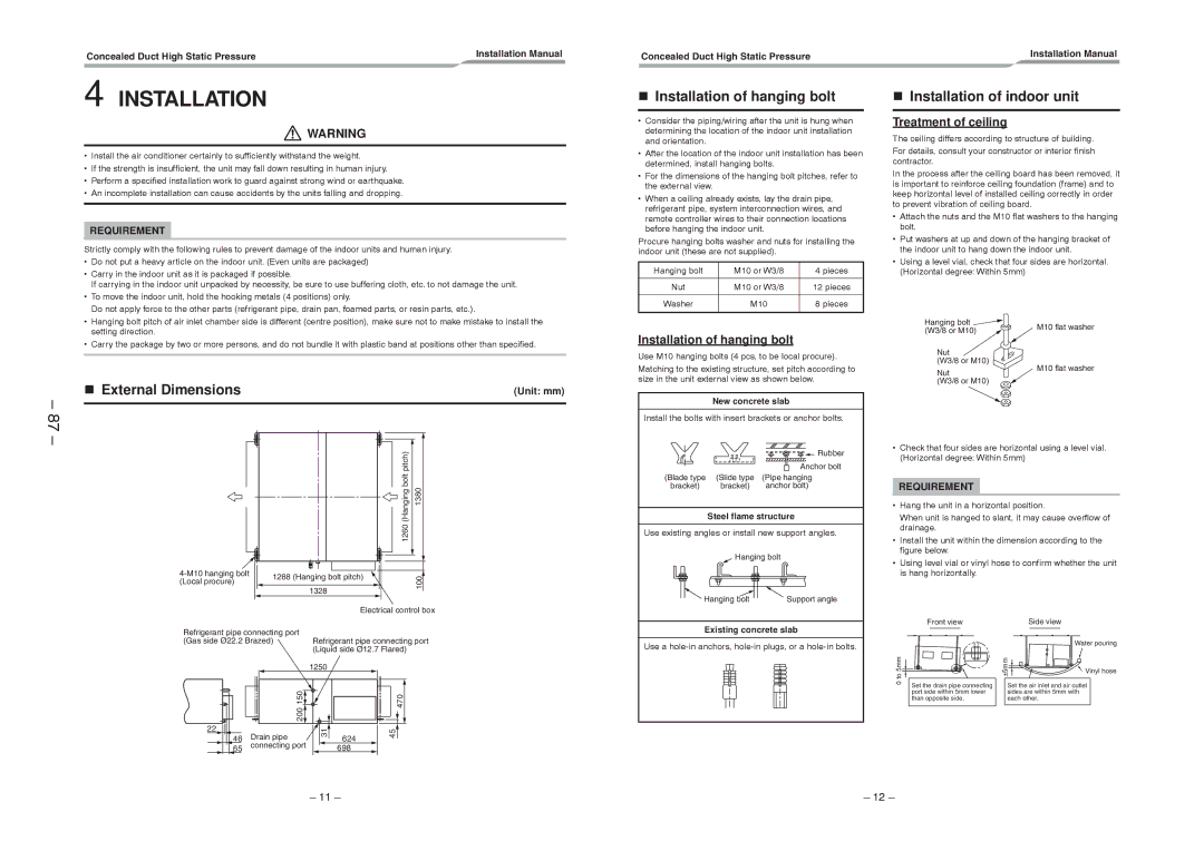
Installation of hanging bolt
External Dimensions
Installation of hanging bolt
Installation of indoor unit
Air outlet port flange
Diagrams for making connecting flanges
Duct installation example First floor
Duct design
FAN Characteristics
RAV-SM2242 Type
RAV-SM2802 Type
Standard Middle static pressure F2
Wire connection change of fan motor
Drain Piping Work
Low static pressure F1
Check the draining
Connecting drain pipe
Pipe material, size and insulator
Drain up
Liquid side refrigerant pipe connection
Refrigerant Piping and Evacuating
Heat insulating process
Refrigerant Piping
Evacuation
Gas side refrigerant pipe connection
Electrical Connection
Wire connection
Wiring diagram
Power and Wiring Specification
Applicable Controls
Remote Controller Wiring
Changing of setting applicable control
Wiring diagram
To secure better effect of heating
Remote controller switch monitoring function
Filter sign setting
Concealed Duct High Static Pressure Procedure
Group control
Procedure example
Manual address setup procedure
Installation Manual Procedure
8C Operation
Procedure
Execute a test run
Daily maintenance
Test RUN
Before test run
Confirmation of error log
Concealed Duct High Static PressureInstallation Manual
Confirmation and check
Status
Error codes and parts to be checked
How to replace the parts Fan assembly and replacement
Part name Work procedure Remarks
Fan assembly
Fan/Fan case
Pull out the fan assembly a fan toward you
104
Fan motor
2242DT-E
Location Description
215, 216 219 218 214218 213
108
Check of Concentration Limit
Toshiba Carrier Corporation