®
Chapter 3 Termination board wiring
Wire optional inputs and outputs
The Tracker controller provides input and output terminals as follows:
•Input for an optional priority shutdown device
•Input for an optional utility pulse meter
•Input for an optional outdoor air temperature sensor
•Output terminal for an optional alarm relay
Refer to Table 6 for input and output wire specifications, and to the termination board wiring diagram in Figure 14 on page 24 for wiring all inputs and outputs.
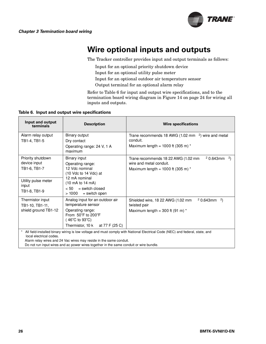
Table 6. Input and output wire specifications
Input and output | Description | Wire specifications | |
terminals | |||
|
| ||
|
|
| |
Alarm relay output | Binary output | Trane recommends 18 AWG (1.02 mm2) wire and metal | |
Dry contact | conduit. | ||
| Operating range: 24 V, 1 A | Maximum length = 1000 ft (305 m) *† | |
| maximum |
| |
|
|
| |
Priority shutdown | Binary input | Trane recommends | |
device input | Operating range: | wire and metal conduit. | |
12 Vdc nominal | Maximum length = 1000 ft (305 m) *‡ | ||
| (10 Vdc to 14 Vdc) at |
| |
| 12 mA nominal |
| |
Utility pulse meter |
| ||
(10 mA to 14 mA) |
| ||
input |
| ||
< 50 Ω = switch closed |
| ||
| |||
> 1000 Ω = switch open |
| ||
|
| ||
|
|
| |
Thermistor input | Analog input for an outdoor air | Shielded wire, | |
temperature sensor | twisted pair | ||
shield ground | Operating range: | Maximum length = 300 ft (91 m) *‡ | |
| From |
| |
|
| ||
| Thermistor, 10 kΩ at 77°F (25°C) |
| |
|
|
|
*All
† Alarm relay wires and 24 Vac wires may reside in the same conduit.
‡ Do not run input wires and ac power wires together in the same conduit or wire bundle.
26 |
|