Manuals
/
Trane
/
Household Appliance
/
Heating System
Trane
Vertical Bypass/Non Bypass Panel Bypass Platform Configurations, Switch Mode Power Supply
Models:
TR200
Vertical Bypass/Non Bypass Panel
1
9
86
86
Download
86 pages
30.73 Kb
6
7
8
9
10
11
12
13
Troubleshooting
Install
Mechanical Diagrams
5.1.8 EMB2 Fault Reporting
Wire Size
Dimension
Panel Configurations
Symptom
Wire and Cable Access
Auto Bypass Function Setup
Page 9
Image 9
Page 8
Page 10
Page 9
Image 9
Page 8
Page 10
Contents
TR200 Vertical Bypass/Non Bypass Panel
Operators Guide
BAS-SVX49A-EN
August
Safety Guidelines
Safety
EQUIPMENT HAZARD
UNINTENDED START
2 Pre-installation
Contents
3 Installation
1 Introduction
4 Start Up
5 Electromechanical Bypass EMB2 Operation
6 Electronically Controlled Bypass ECB Operation
8 Appendix
7 Start Up Troubleshooting
BAS-SVX49A-EN
Contents
1.1.1 Purpose of the Manual
1 Introduction
1.1.2 Overview
1.1.3 Typical Bypass Operation
1.3.1 Common Run/Stop with Bypass
1.3 Bypass Options
1.3.2 Automatic Bypass
1.3.3 Run Permissive in Bypass
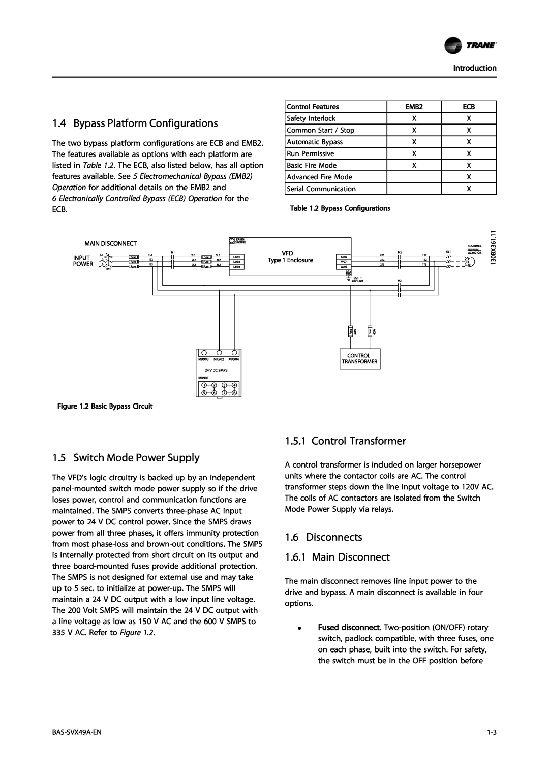
1.5 Switch Mode Power Supply
1.4 Bypass Platform Configurations
1.5.1 Control Transformer
1.6 Disconnects 1.6.1 Main Disconnect
Introduction
1.6.2 Mode Selector Switch
Table 1.3 Tier Definitions and Features
1.6.3 Panel Configurations
Introduction
Non bypass
1.6.4 Panel Voltage and Frame Ratings
1.7Power Component Functions 1.7.1 Power Fusing
Main fusing
Drive fusing
2.1.2 Pre-installationCheck
2 Pre-installation
2.1.3 Installation Site Check
2.1.1 Receiving Inspection
2.2.1 Airborne Liquids
2.2Harsh Environments
2.2.2 Airborne Solids
2.2.3 Corrosive Chemicals
3.1.1 Tools Required
3 Installation
3.1.2 Drive Fuses
Installation
230 V AC
Installation
460 V AC
600 V AC
3.2.4 Shipping Weights
3.2Mechanical Installation 3.2.1 Lifting
3.1.3 Internal Main Panel Fuses
3.2.3 Forklift
Installation
3.3 Cooling
Figure 3.2 Side Cooling Clearance
Figure 3.1 Proper Lifting Method
Proper Field Wiring and Grounding Required
3.4 Electrical Installation
Hazardous Voltage
INDUCED VOLTAGE
Installation
Figure 3.4 Power Connections
BAS-SVX49A-EN
Installation
Figure 3.5 P2 Bypass Mechanical Layout Diagram
Table 3.8 Reference Designator Definitions
BAS-SVX49A-EN
Installation
Installation
Figure 3.7 P3 Bypass Mechanical Layout Diagram
BAS-SVX49A-EN
Installation
3-10
BAS-SVX49A-EN
Figure 3.9 P4 Bypass Mechanical Layout Diagram
Installation
BAS-SVX49A-EN
3-11
Installation
3-12
BAS-SVX49A-EN
Figure 3.11 P5 Bypass Mechanical Layout Diagram
Installation
BAS-SVX49A-EN
3-13
Installation
3-14
BAS-SVX49A-EN
Installation
3.4.2 Wire and Cable Access
Hazardous Voltage
IMPORTANT NOTE
Figure 3.15 P2 Panel Figure 3.16 P3 Panel
Installation
3-16
BAS-SVX49A-EN
Figure 3.17 P4 Panel
Installation
BAS-SVX49A-EN
3-17
Figure 3.18 P5 Panel
Installation
3-18
BAS-SVX49A-EN
Installation
3.4.3 Wire Size
3.4.4 Wire Type Rating
3.4.5 Terminal Tightening Torques
Installation
Non Bypass
Installation
Bypass
HP KW
Ground Wire
Installation
230 V AC
Non Bypass
Ground Wire
Installation
460 VAC
Output
Ground Wire
Installation
600 VAC
Non Bypass
3.4.6 Input Line Connection
3.4.7 Motor Wiring
Installation
Hazardous Voltage
3.4.8 Grounding Earthing
3.4.9 Control Wiring
Installation
Field Wiring
3.4.10Serial Communication Bus Connection
Installation
Programming
Installation
3.4.11 Drive Control Terminals
4 Start Up
HAZARDOUS VOLTAGE
Start Up
4.1.1 Inspection Prior to Start Up
4.1.2 Start Up Procedure
HAZARDOUS VOLTAGE
Start Up
Start Up
MOTOR START
BAS-SVX49A-EN
Start Up
Electromechanical Bypass EMB2 Operation
5 Electromechanical Bypass EMB2 Operation
BAS-SVX49A-EN
Electromechanical Bypass E
5.1.3 EMB2 Common Run/Stop
5.1.2 EMB2 Auto Bypass
Auto Bypass Function Setup
Common Run/Stop Setup
5.1.5 EMB2 Overload
5.1.4 EMB2 Run Permissive
MOTOR DAMAGE
Run Permissive Function Setup
5.1.8 EMB2 Fault Reporting
5.1.6 EMB2 Safety Interlock
5.1.7 EMB2 Fire Mode
Safety Interlock Function Setup
Fault Reporting Function Setup
5.1.9 EMB2 Switches
Mode selector switch
Electromechanical Bypass E
6 Electronically Controlled Bypass ECB Operation
6.1Electronically Controlled Bypass ECB Operation
6.1.1 Overview
6.1.2 ECB Control Card
1 2 3 4
Electronically Controlled B
Figure 6.2 ECB Control Card Terminal Connections
BAS-SVX49A-EN
Electronically Controlled Bypass ECB Opera- tion
Input Conn
Electronically Controlled B
Term
Function
6.1.3 ECB Drive or Bypass Selection
Electronically Controlled B
BAS-SVX49A-EN
130BX238.10
6.1.4 ECB Programming
6.1.6 ECB Mode of Operation
6.1.5 ECB Hand/OFF/Auto
Electronically Controlled B
General Information
Par. No
Mode of Operation Select
Selection
Function
6.1.8 ECB Auto Bypass
6.1.7 Bypass Status Word Bit Examples
Auto Bypass Function Setup
Electronically Controlled B
6.1.10 ECB Overload
6.1.9 ECB Run Permissive
Run Permissive Function Setup
Disable Run Permissive
6.1.12 ECB Common Run/Stop
6.1.11 ECB Safety Interlock
Safety Interlock Function Setup
Overload Function Setup
6.1.13 ECB Advanced Fire Mode
6.1.14 ECB Fault Reporting
Fire Mode Function Setup
Fault Reporting Function Setup
Electronically Controlled B
6-14
BAS-SVX49A-EN
7.1.1 Option Panel Alarm and Warnings
7 Start Up Troubleshooting
Start Up Troubleshooting
Code
Symptom
Start Up Troubleshooting
Solution
Table 7.3 Fault Table
Solution
Symptom
Possible cause
Test
Symptom
Start Up Troubleshooting
Solution
Possible cause
8.1.1 Dimensions
8 Appendix
P2 BYPASS
P3 BYPASS
8.1.2 Mechanical Diagrams
Appendix
Figure 8.1 P2 Bypass
Appendix
Figure 8.2 P2 Non-bypass
BAS-SVX49A-EN
Appendix
BAS-SVX49A-EN
Figure 8.3 P3 P4 P5 Bypass
Appendix
Figure 8.4 P3 P4 P5 Non-bypass
BAS-SVX49A-EN
8.1.3 Typical Wiring Diagrams
Appendix
Figure 8.5 EMB2 with Control Relay, Part
Appendix
Figure 8.6 EMB2 with Control Relay, Part
BAS-SVX49A-EN
Appendix
Figure 8.7 EMB2, Part
BAS-SVX49A-EN
Appendix
BAS-SVX49A-EN
Figure 8.8 EMB2, Part
Figure 8.9 ECB, Part
Appendix
8-10
BAS-SVX49A-EN
Figure 8.10 ECB, Part
Appendix
BAS-SVX49A-EN
8-11
Figure 8.11 ECB with Control Relays, Part
Appendix
8-12
BAS-SVX49A-EN
Figure 8.12 ECB with Control Relays, Part
Appendix
BAS-SVX49A-EN
8-13
Figure 8.13 Non-bypass
Appendix
8-14
BAS-SVX49A-EN
Page
177R0253
MG14D122 *MG14D122
Top
Page
Image
Contents