Introduction
Components
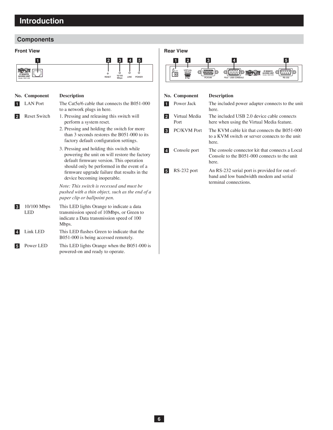
Front View
1 |
| 2 |
| 3 |
| 4 |
| 5 | |||||
|
|
|
|
|
|
|
|
|
|
|
|
|
|
|
|
|
|
|
|
|
|
|
|
|
|
|
|
No.. | Component | Description | |
|
| LAN Port | The Cat5e/6 cable that connects the |
1 |
| ||
|
|
| to a network plugs in here. |
|
| Reset Switch | 1. Pressing and releasing this switch will |
2 |
| ||
|
|
| perform a system reset. |
|
|
| 2. Pressing and holding the switch for more |
|
|
| than 3 seconds restores the |
|
|
| factory default configuration settings. |
|
|
| 3. Pressing and holding this switch while |
|
|
| powering the unit on will restore the factory |
|
|
| default firmware version. This operation |
|
|
| should only be performed in the event of a |
|
|
| firmware upgrade failure that results in the |
|
|
| device becoming inoperable. |
|
|
| Note: This switch is recessed and must be |
|
|
| pushed with a thin object, such as the end of a |
|
|
| paper clip or ballpoint pen. |
|
| 10/100 Mbps | This LED lights Orange to indicate a data |
3 |
| ||
|
| LED | transmission speed of 10Mbps, or Green to |
|
|
| indicate a Data transmission speed of 100 |
|
|
| Mbps. |
|
| Link LED | This LED flashes Green to indicate that the |
4 |
| ||
|
|
| |
|
| Power LED | This LED lights Orange when the |
5 |
| ||
|
|
| |
Rear View
|
| 1 |
| 2 |
| 3 |
| 4 |
|
| 5 |
|
|
| |||||
|
|
|
|
|
|
|
|
|
|
|
|
|
|
|
|
|
|
|
|
|
|
|
|
|
|
|
|
|
|
|
|
|
|
|
|
|
|
|
|
|
|
|
|
|
|
|
|
|
|
|
|
|
|
|
|
|
|
|
|
|
|
|
|
|
|
|
|
|
|
|
|
|
|
|
|
|
|
|
|
|
|
|
|
|
|
|
|
|
|
|
|
|
|
|
|
|
|
|
|
No.. | Component | Description | |
|
| Power Jack | The included power adapter connects to the unit |
1 |
| ||
|
|
| here. |
|
| Virtual Media | The included USB 2.0 device cable connects |
2 |
| ||
|
| Port | here when using the Virtual Media feature. |
|
| PC/KVM Port | The KVM cable kit that connects the |
3 |
| ||
|
|
| to a KVM switch or server connects to the unit |
|
|
| here. |
|
| Console port | The console connector kit that connects a Local |
4 |
| ||
|
|
| Console to the |
|
|
| here. |
|
| An | |
5 |
| ||
|
|
| band and low bandwidth modem and serial |
|
|
| terminal connections. |
6