VXI VT1538A user manual VRS Mode Input Operation SCP channels 0 & 1 only

Models: VT1538A

1 84
Download 84 pages 24.07 Kb
Page 14
Image 14
VRS Mode

is to maintain a constant-level digital output while the input varies from millivolts to several tens of volts.

For simple sensing of switches and open collector logic devices, a channel’s pull-up resistor can be connected by closing its PU switch.

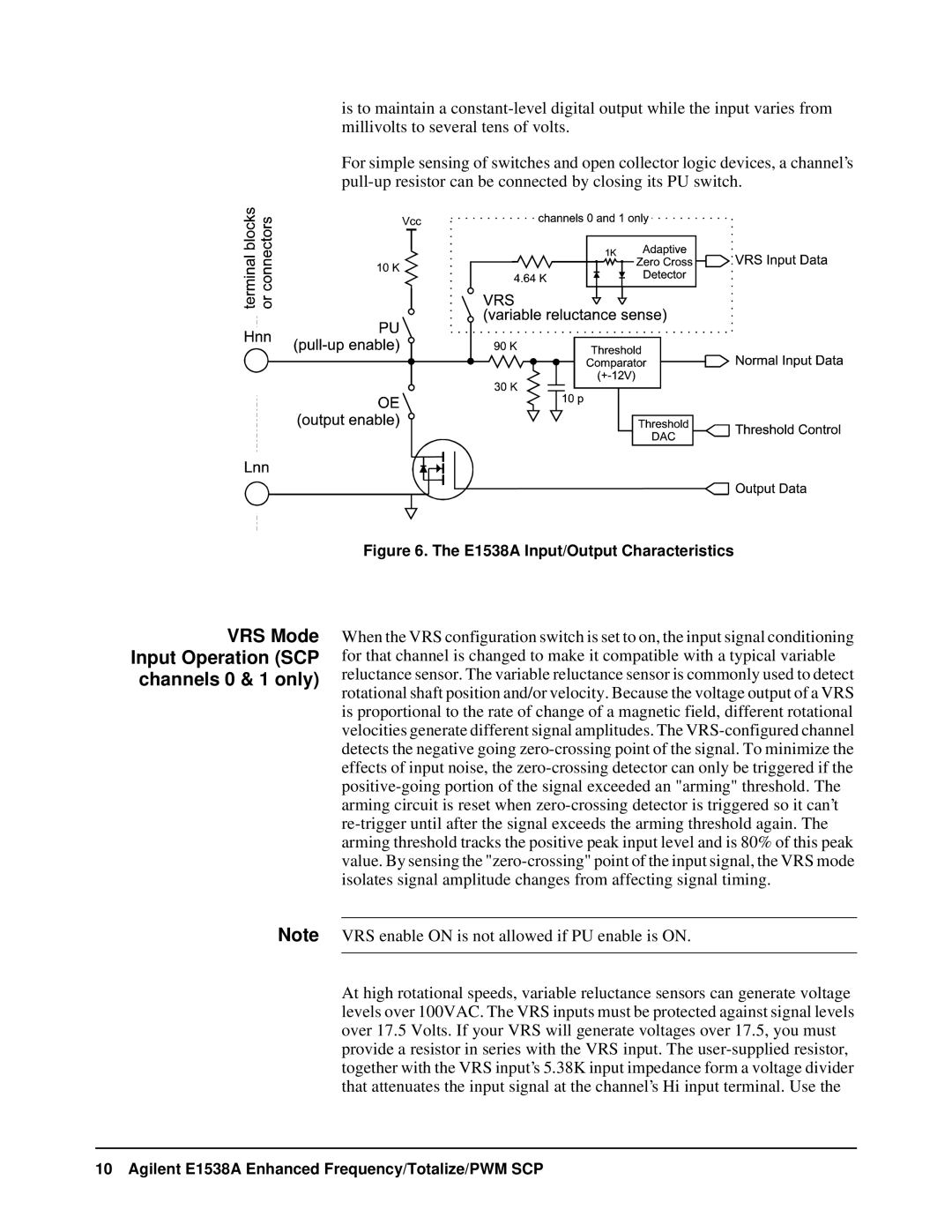
Figure 6. The E1538A Input/Output Characteristics

VRS Mode

Input Operation (SCP

channels 0 & 1 only)

When the VRS configuration switch is set to on, the input signal conditioning for that channel is changed to make it compatible with a typical variable reluctance sensor. The variable reluctance sensor is commonly used to detect rotational shaft position and/or velocity. Because the voltage output of a VRS is proportional to the rate of change of a magnetic field, different rotational velocities generate different signal amplitudes. The VRS-configured channel detects the negative going zero-crossing point of the signal. To minimize the effects of input noise, the zero-crossing detector can only be triggered if the positive-going portion of the signal exceeded an "arming" threshold. The arming circuit is reset when zero-crossing detector is triggered so it can’t re-trigger until after the signal exceeds the arming threshold again. The arming threshold tracks the positive peak input level and is 80% of this peak value. By sensing the "zero-crossing" point of the input signal, the VRS mode isolates signal amplitude changes from affecting signal timing.

Note VRS enable ON is not allowed if PU enable is ON.

At high rotational speeds, variable reluctance sensors can generate voltage levels over 100VAC. The VRS inputs must be protected against signal levels over 17.5 Volts. If your VRS will generate voltages over 17.5, you must provide a resistor in series with the VRS input. The user-supplied resistor, together with the VRS input’s 5.38K input impedance form a voltage divider that attenuates the input signal at the channel’s Hi input terminal. Use the

10 Agilent E1538A Enhanced Frequency/Totalize/PWM SCP

Page 14
Image 14
VXI VT1538A user manual VRS Mode Input Operation SCP channels 0 & 1 only