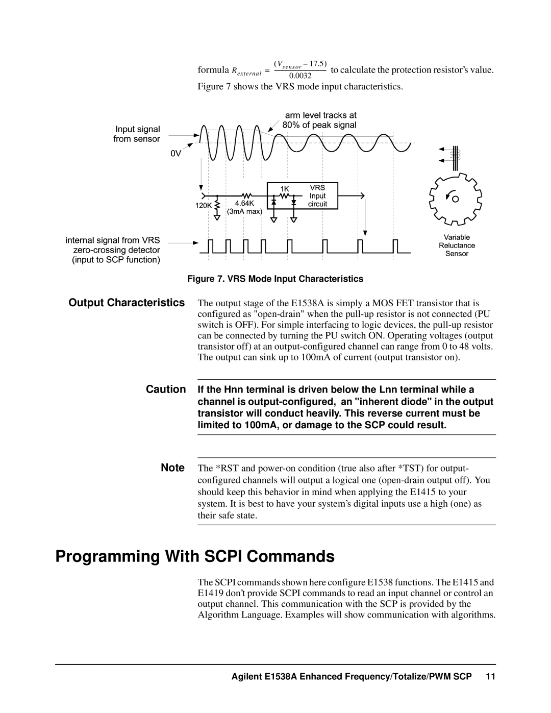
formula(Vs en sor – 17.5) to calculate the protection resistor’s value. Rext er na l = --------------------------------------
0.0032
Figure 7 shows the VRS mode input characteristics.
Figure 7. VRS Mode Input Characteristics
Output Characteristics The output stage of the E1538A is simply a MOS FET transistor that is configured as "open-drain" when the pull-up resistor is not connected (PU switch is OFF). For simple interfacing to logic devices, the pull-up resistor can be connected by turning the PU switch ON. Operating voltages (output transistor off) at an output-configured channel can range from 0 to 48 volts. The output can sink up to 100mA of current (output transistor on).
Caution If the Hnn terminal is driven below the Lnn terminal while a channel is output-configured, an "inherent diode" in the output transistor will conduct heavily. This reverse current must be limited to 100mA, or damage to the SCP could result.
Note The *RST and power-on condition (true also after *TST) for output- configured channels will output a logical one (open-drain output off). You should keep this behavior in mind when applying the E1415 to your system. It is best to have your system’s digital inputs use a high (one) as their safe state.
Programming With SCPI Commands
The SCPI commands shown here configure E1538 functions. The E1415 and E1419 don’t provide SCPI commands to read an input channel or control an output channel. This communication with the SCP is provided by the Algorithm Language. Examples will show communication with algorithms.
Agilent E1538A Enhanced Frequency/Totalize/PWM SCP 11