Programming Output Channels
Controlling Output Polarity
This section deals with all aspects of programming output channel functions. Channels are configured for output with the I/O direction switches (see "Configuring
Use OUTPut:POLarity NORMal INVerted,(@<ch_list>) to configure output channel logic sense. The operations is as follows:
OUTP:POL NORM | a logical 1 output from the algorithm, or generated |
| within the E1538 (single or repetitive pulses) will |
| turn off the output transistor (can be pulled up). |
OUT:POL INV | a logical 1 output from the algorithm, or generated |
| within the E1538 (single or repetitive pulses) will turn |
| off the output transistor (pulls low). |
To configure channels 40 to 43 to drive their outputs low for a logic 1
OUTP:POL INV,(@140:143)
Output Static Digital State
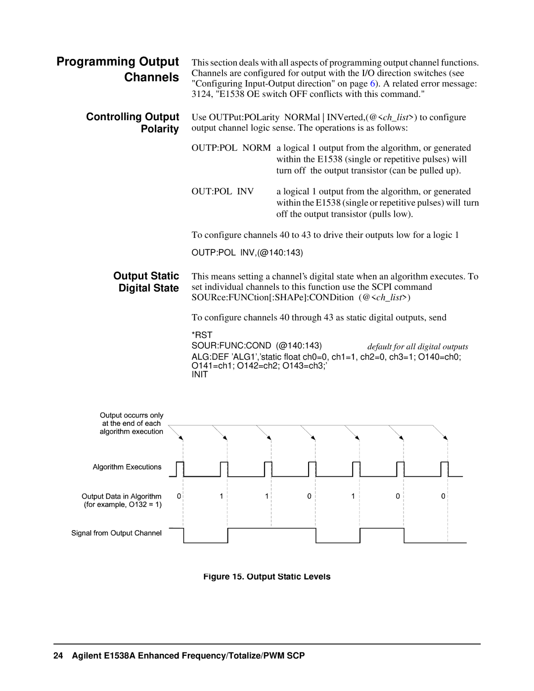
This means setting a channel’s digital state when an algorithm executes. To set individual channels to this function use the SCPI command SOURce:FUNCtion[:SHAPe]:CONDition (@<ch_list>)
To configure channels 40 through 43 as static digital outputs, send
*RST |
|
SOUR:FUNC:COND (@140:143) | default for all digital outputs |
ALG:DEF ’ALG1’,’static float ch0=0, ch1=1, ch2=0, ch3=1; O140=ch0; O141=ch1; O142=ch2; O143=ch3;’