Model MRC44 | Page: 19 |
(EXPANDED)
When at least one zone on either the PRIMARY or SECONDARY controller is turned ON, the Control Out on the PRIMARY Controller is High (+12 volts). The Control Out on the SECONDARY Controller will be inactive.
AC Power Connections
(BASIC/ADVANCED/EXPANDED)
Use the supplied power cable and plug into a power source capable of delivering the rated amps shown in the specification section of this manual.
CONNECTIONS AT THE ZONE LOCATION (BASIC/ADVANCED/EXPANDED)
Single Keypad Connections
1.Refer to Figure 10 for proper termination at the
2.Connect the CAT5 cable from the MRC44 Controller/Amplifier into the RJ45 jack marked “Controller” on the rear of the MRC44 keypad.
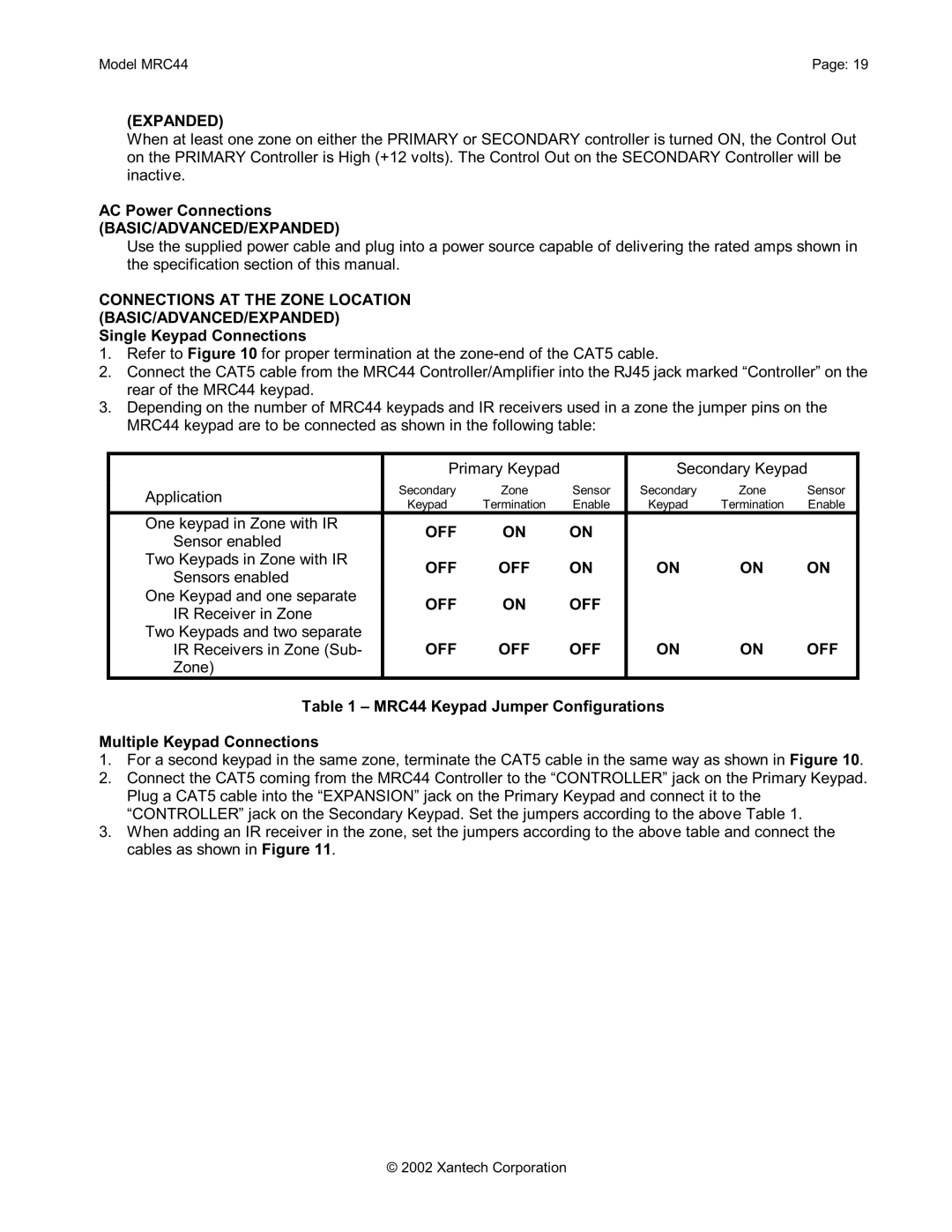
3.Depending on the number of MRC44 keypads and IR receivers used in a zone the jumper pins on the MRC44 keypad are to be connected as shown in the following table:
| Primary Keypad |
| Secondary Keypad | ||||
Application | Secondary | Zone | Sensor | Secondary | Zone | Sensor | |
Keypad | Termination | Enable | Keypad | Termination | Enable | ||
| |||||||
One keypad in Zone with IR | OFF | ON | ON |
|
|
| |
Sensor enabled |
|
|
| ||||
|
|
|
|
|
| ||
Two Keypads in Zone with IR | OFF | OFF | ON | ON | ON | ON | |
Sensors enabled | |||||||
|
|
|
|
|
| ||
One Keypad and one separate | OFF | ON | OFF |
|
|
| |
IR Receiver in Zone |
|
|
| ||||
|
|
|
|
|
| ||
Two Keypads and two separate |
|
|
|
|
|
| |
IR Receivers in Zone (Sub- | OFF | OFF | OFF | ON | ON | OFF | |
Zone) |
|
|
|
|
|
| |
Table 1 – MRC44 Keypad Jumper Configurations
Multiple Keypad Connections
1.For a second keypad in the same zone, terminate the CAT5 cable in the same way as shown in Figure 10.
2.Connect the CAT5 coming from the MRC44 Controller to the “CONTROLLER” jack on the Primary Keypad. Plug a CAT5 cable into the “EXPANSION” jack on the Primary Keypad and connect it to the “CONTROLLER” jack on the Secondary Keypad. Set the jumpers according to the above Table 1.
3.When adding an IR receiver in the zone, set the jumpers according to the above table and connect the cables as shown in Figure 11.
© 2002 Xantech Corporation
