Operating Manual
XFR 2800 Watt Series Programmable DC Power Supply
XFR XFR XFR XFR XFR XFR XFR XFR XFR XFR
Page
Operating Manual for
XFR 2800 Watt Series
Programmable DC Power Supply
Limited Warranty
How do you get service?
Proof of purchase may be in any one of the following forms
Disclaimer Product
WARNING Limitations on Use
Information About Your Power Supply
Cautions
Power Supply Safety
About This Manual
Who Should Use This Manual
Main Sections
Manual Revisions
About This Manual
Power Supply Safety Markings
Section Features and Specifications
Contents
Section 5. Calibration
Section Local Operation Section Remote Operation
List of Figures
List of Figures
Operating Manual for XFR 2.8kW Series Power Supply
List of Tables
List of Tables
Operating Manual for XFR 2.8kW Series Power Supply
Description
Section 1. Features and Specifications
Features and Options
External monitor signals for output voltage and current
Section 3. Local Operation
Front Panel Controls
“Mechanical Specifications” on page “Functional Tests” on page
Rear Panel Connectors and Switch
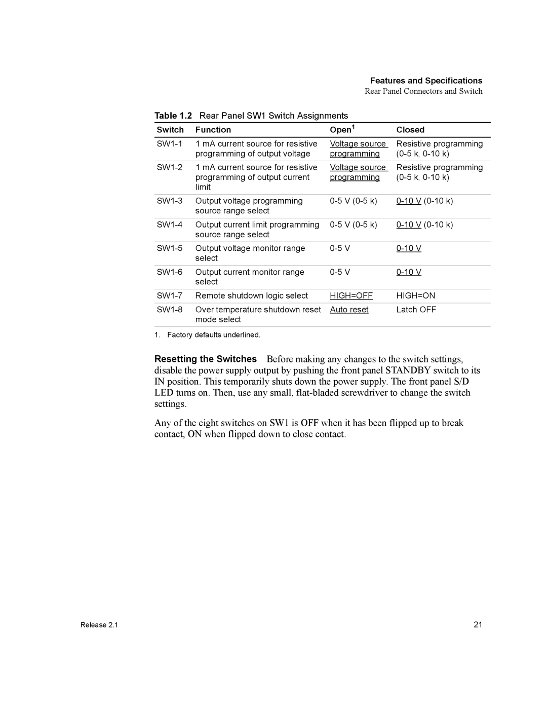
Low voltage 7.5 V to 100 V model shown
Figure 1.2 Power Supply Rear Panel
switch enables you to choose
Resetting the Switches Before making any changes to the switch settings, disable the power supply output by pushing the front panel STANDBY switch to its IN position. This temporarily shuts down the power supply. The front panel S/D LED turns on. Then, use any small, flat-bladed screwdriver to change the switch settings
provides access to the following functions
Name
Features and Specifications
Connector
Reference
Making J2 Connections
Wiring
Nominal line voltage is 208 Vac, 60 Hz
Specifications
Specifications are subject to change without notice
12-220
Features and Specifications
Models
7.5-300
Specifications
Features and Specifications
100-28
Features and Specifications
Models
60-46
Specifications
Features and Specifications
Based on 100 V, 28 A model
Input Conditions
Additional Specifications
Remote Programming and Monitoring
Additional Features
Environmental Specifications
Mechanical Specifications
3.45 87.63 mm
Figure 1.6 Dimensional Drawings
Dimensions given are nominal
Operating Manual for XFR 2.8kW Series Power Supply
Introduction
Section 2. Installation
Basic Setup Procedure
Initial Inspection Periodic Cleaning
Inspection, Cleaning, and Packaging
If you are returning a product from outside of the USA or Canada
Returning Power Supplies to the Manufacturer
Packaging for Shipping or Storage
Rack Mounting
Location, Mounting, and Ventilation
AC Input
AC Input Power
AC Input Connector and Voltage Selection
60 C minimum, 300
AC Input Wire Connection
Table 2.3 AC Wire Specification
3 x 12 AWG stranded copper
AC Input Cover and Strain Relief
Functional Tests
Voltage Mode Operation Check
Current Mode Operation Check Front Panel Function Checks
Load Connection
Load Wiring
Figure 2.3 Maximum Load Wire Length for 1 V Line Drop
Making Load Connections
To detach the 2-part cover
1. Strip the ends of the wires
150 V to 600 V Models
Figure 2.6 Output Voltage Connector
sense connector as identified on Figure 1.2, on page
Loads the radial power distribution method
Figure 2.10Multiple Loads with Remote Sensing
Installation
Operating Manual for XFR 2.8kW Series Power Supply
Local and Remote Sensing
Sense Wiring
Function
Installation
Terminal
Name
Using Remote Sensing
5. Turn the power supply ON
Introduction
Section 3. Local Operation
Standard Operation
Operating Modes and Automatic Crossover
Figure 3.1 Operating Modes
Local Operation
front and rear panel diagrams
Setting Output Voltage and Current Limit
Front Panel OVP Operation
Using Over Voltage Protection OVP
To reset the OVP circuit after it activates
Controlling the Shutdown Function via the J2 Connector
Using the Shutdown Function
1. If switch SW1-7 is ON but there is no signal applied, the S/D LED turns on and the power supply will not provide an output until the HIGH signal level is applied
Configuring Multiple Supplies for Series Operation
Using Multiple Supplies
Operation
Configuring
Multiple
Parallel
Supplies for Split Supply Operation
Figure 3.4 Split Supply Operation of Multiple Supplies
Positive-negative Supply
Figure 3.5 Split Supply Operation of Multiple Supplies
Local sense lines shown are default J10 connections
Positive-negative Supply
Over Temperature Protection OTP
Unusual or Erratic Operation
User Diagnostics
Emergency Shutdown
Further Checks and Corrections
Symptom
Local Operation
Check
Introduction
Section 4. Remote Operation
Programming
Procedure
Remote Analog Programming of Output Voltage and Current Limit
Remote
4. Connect the programming sources to the mating J2 connector as shown in Figure 4.1, observing the correct polarity for voltage sources. Ensure that the mating connector is plugged securely into the rear panel connector
Remote Operation
Remote Operation
Figure 4.1 Connecting Programming Sources to J2 Connector
Remote Monitoring of Output Voltage and Current
Section 5. Calibration
Calibration Setup
Service
Precautions
Calibration
Calibration Setup
Accessing Calibration Potentiometers
Tool Required Phillips #2 screwdriver
Voltage Programming Circuit Calibration
Calibrating for Programming Accuracy
Current Limit Programming Circuit Calibration
Output Voltage Monitor Circuit Calibration
Calibrating for Readback Accuracy
Output Current Monitor Circuit Calibration
Calibrating for Readback Accuracy
Operating Manual for XFR 2.8kW Series Power Supply
Calibration
Page
800 667 8422 Toll Free North America prg.info@xantrex.com
Xantrex Technology Inc
8999 Nelson Way Burnaby, British Columbia Canada V5A 4B5
604 422 8595 Tel 604 421 3056 Fax