|
| Local Operation |
|
| Standard Operation |
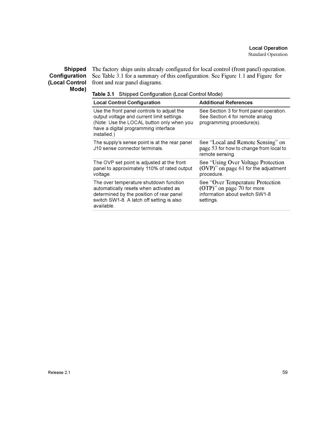
Shipped | The factory ships units already configured for local control (front panel) operation. | |
Configuration | See Table 3.1 for a summary of this configuration. See Figure 1.1 and Figure for | |
(Local Control | front and rear panel diagrams. |
|
Mode) | Table 3.1 Shipped Configuration (Local Control Mode) | |
| Local Control Configuration | Additional References |
Use the front panel controls to adjust the output voltage and current limit settings. (Note: Use the LOCAL button only when you have a digital programming interface installed.)
See Section 3 for front panel operation. See Section 4 for remote analog programming procedure(s).
The supply's sense point is at the rear panel | See “Local and Remote Sensing” on |
J10 sense connector terminals. | page 53 for how to change from local to |
| remote sensing. |
The OVP set point is adjusted at the front | See “Using Over Voltage Protection |
panel to approximately 110% of rated output | (OVP)” on page 61 for the adjustment |
voltage. | procedure. |
The over temperature shutdown function | See “Over Temperature Protection |
automatically resets when activated as | (OTP)” on page 70 for more |
determined by the position of rear panel | information about switch |
switch | settings. |
available. |
|
Release 2.1 | 59 |
