Features and Specifications
Specifications
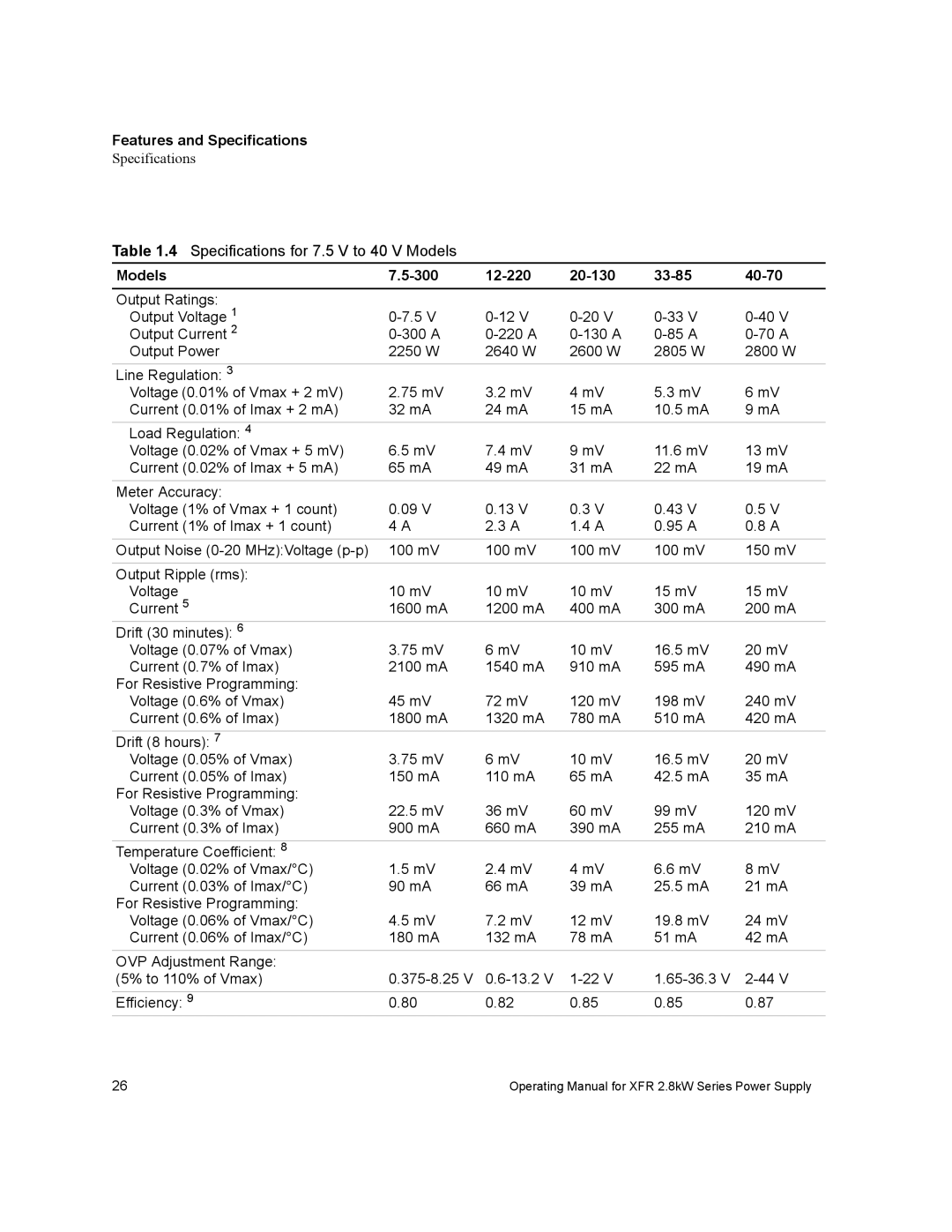
Table 1.4 Specifications for 7.5 V to 40 V Models
Models |
|
|
|
|
|
Output Ratings: |
|
|
|
|
|
Output Voltage 1 | |||||
Output Current 2 | |||||
Output Power | 2250 W | 2640 W | 2600 W | 2805 W | 2800 W |
|
|
|
|
|
|
Line Regulation: 3 |
|
|
|
|
|
Voltage (0.01% of Vmax + 2 mV) | 2.75 mV | 3.2 mV | 4 mV | 5.3 mV | 6 mV |
Current (0.01% of Imax + 2 mA) | 32 mA | 24 mA | 15 mA | 10.5 mA | 9 mA |
|
|
|
|
|
|
Load Regulation: 4 |
|
|
|
|
|
Voltage (0.02% of Vmax + 5 mV) | 6.5 mV | 7.4 mV | 9 mV | 11.6 mV | 13 mV |
Current (0.02% of Imax + 5 mA) | 65 mA | 49 mA | 31 mA | 22 mA | 19 mA |
|
|
|
|
|
|
Meter Accuracy: |
|
|
|
|
|
Voltage (1% of Vmax + 1 count) | 0.09 V | 0.13 V | 0.3 V | 0.43 V | 0.5 V |
Current (1% of Imax + 1 count) | 4 A | 2.3 A | 1.4 A | 0.95 A | 0.8 A |
|
|
|
|
|
|
Output Noise | 100 mV | 100 mV | 100 mV | 100 mV | 150 mV |
|
|
|
|
|
|
Output Ripple (rms): |
|
|
|
|
|
Voltage | 10 mV | 10 mV | 10 mV | 15 mV | 15 mV |
Current 5 | 1600 mA | 1200 mA | 400 mA | 300 mA | 200 mA |
Drift (30 minutes): 6 |
|
|
|
|
|
Voltage (0.07% of Vmax) | 3.75 mV | 6 mV | 10 mV | 16.5 mV | 20 mV |
Current (0.7% of Imax) | 2100 mA | 1540 mA | 910 mA | 595 mA | 490 mA |
For Resistive Programming: |
|
|
|
|
|
Voltage (0.6% of Vmax) | 45 mV | 72 mV | 120 mV | 198 mV | 240 mV |
Current (0.6% of Imax) | 1800 mA | 1320 mA | 780 mA | 510 mA | 420 mA |
Drift (8 hours): 7 |
|
|
|
|
|
Voltage (0.05% of Vmax) | 3.75 mV | 6 mV | 10 mV | 16.5 mV | 20 mV |
Current (0.05% of Imax) | 150 mA | 110 mA | 65 mA | 42.5 mA | 35 mA |
For Resistive Programming: |
|
|
|
|
|
Voltage (0.3% of Vmax) | 22.5 mV | 36 mV | 60 mV | 99 mV | 120 mV |
Current (0.3% of Imax) | 900 mA | 660 mA | 390 mA | 255 mA | 210 mA |
Temperature Coefficient: 8 |
|
|
|
|
|
Voltage (0.02% of Vmax/°C) | 1.5 mV | 2.4 mV | 4 mV | 6.6 mV | 8 mV |
Current (0.03% of Imax/°C) | 90 mA | 66 mA | 39 mA | 25.5 mA | 21 mA |
For Resistive Programming: |
|
|
|
|
|
Voltage (0.06% of Vmax/°C) | 4.5 mV | 7.2 mV | 12 mV | 19.8 mV | 24 mV |
Current (0.06% of Imax/°C) | 180 mA | 132 mA | 78 mA | 51 mA | 42 mA |
OVP Adjustment Range: |
|
|
|
|
|
(5% to 110% of Vmax) | |||||
|
|
|
|
|
|
Efficiency: 9 | 0.80 | 0.82 | 0.85 | 0.85 | 0.87 |
26 | Operating Manual for XFR 2.8kW Series Power Supply |