Installation
Load Connection
Load Connection
This section provides recommendations for load wires and how to connect them for both single and multiple load configurations.
Load Wiring
WARNING
Ensure that the chassis ground screw does not penetrate more than 3/8 in. (9 mm) into the rear panel of the unit.
When connecting load wiring to the power supply, consider the following factors:
•insulation rating of the wire
•current carrying capacity of the wire
•maximum load wiring length for operation with sense lines
•noise and impedance effects of the load lines
Insulation Rating Use load wiring with a minimum insulation rating equivalent to the maximum output voltage of the power supply. For example, select
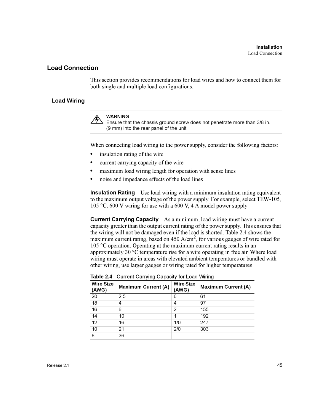
Current Carrying Capacity As a minimum, load wiring must have a current capacity greater than the output current rating of the power supply. This ensures that the wiring will not be damaged even if the load is shorted. Table 2.4 shows the maximum current rating, based on 450 A/cm2, for various gauges of wire rated for 105 °C operation. Operating at the maximum current rating results in an approximately 30 °C temperature rise for a wire operating in free air. Where load wiring must operate in areas with elevated ambient temperatures or bundled with other wiring, use larger gauges or wiring rated for higher temperatures.
Table 2.4 Current Carrying Capacity for Load Wiring
Wire Size | Maximum Current (A) |
| Wire Size | Maximum Current (A) |
(AWG) |
| (AWG) | ||
20 | 2.5 |
| 6 | 61 |
18 | 4 |
| 4 | 97 |
16 | 6 |
| 2 | 155 |
14 | 10 |
| 1 | 192 |
12 | 16 |
| 1/0 | 247 |
10 | 21 |
| 2/0 | 303 |
8 | 36 |
|
|
|
Release 2.1 | 45 |
