Local Operation
User Diagnostics
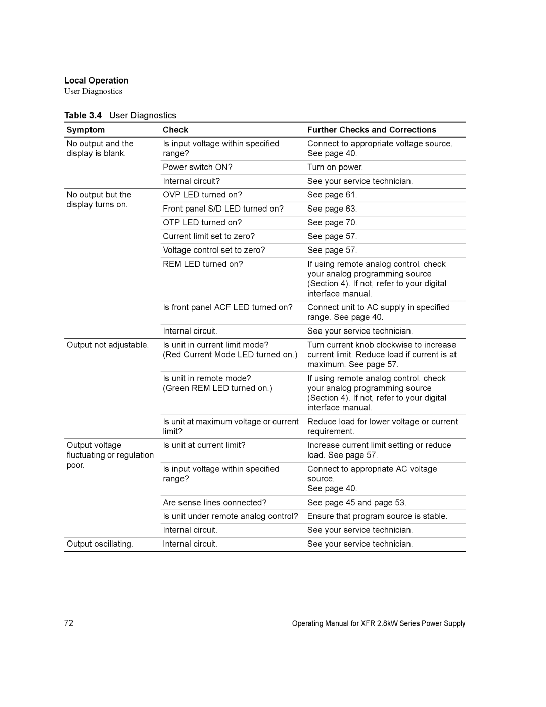
Table 3.4 User Diagnostics
Symptom | Check | Further Checks and Corrections | |
No output and the | Is input voltage within specified | Connect to appropriate voltage source. | |
display is blank. | range? | See page 40. | |
|
|
| |
| Power switch ON? | Turn on power. | |
|
|
| |
| Internal circuit? | See your service technician. | |
|
|
| |
No output but the | OVP LED turned on? | See page 61. | |
display turns on. |
|
| |
Front panel S/D LED turned on? | See page 63. | ||
| |||
|
|
| |
| OTP LED turned on? | See page 70. | |
|
|
| |
| Current limit set to zero? | See page 57. | |
|
|
| |
| Voltage control set to zero? | See page 57. | |
|
|
| |
| REM LED turned on? | If using remote analog control, check | |
|
| your analog programming source | |
|
| (Section 4). If not, refer to your digital | |
|
| interface manual. | |
| Is front panel ACF LED turned on? | Connect unit to AC supply in specified | |
|
| range. See page 40. | |
| Internal circuit. | See your service technician. | |
|
|
| |
Output not adjustable. | Is unit in current limit mode? | Turn current knob clockwise to increase | |
| (Red Current Mode LED turned on.) | current limit. Reduce load if current is at | |
|
| maximum. See page 57. |
Is unit in remote mode? (Green REM LED turned on.)
If using remote analog control, check your analog programming source (Section 4). If not, refer to your digital interface manual.
| Is unit at maximum voltage or current | Reduce load for lower voltage or current | |
| limit? | requirement. | |
Output voltage | Is unit at current limit? | Increase current limit setting or reduce | |
fluctuating or regulation |
| load. See page 57. | |
poor. |
|
| |
Is input voltage within specified | Connect to appropriate AC voltage | ||
| |||
| range? | source. | |
|
| See page 40. | |
| Are sense lines connected? | See page 45 and page 53. | |
|
| ||
| Is unit under remote analog control? Ensure that program source is stable. | ||
|
|
| |
| Internal circuit. | See your service technician. | |
|
|
| |
Output oscillating. | Internal circuit. | See your service technician. | |
|
|
| |
72 | Operating Manual for XFR 2.8kW Series Power Supply |