Features and Specifications
Specifications
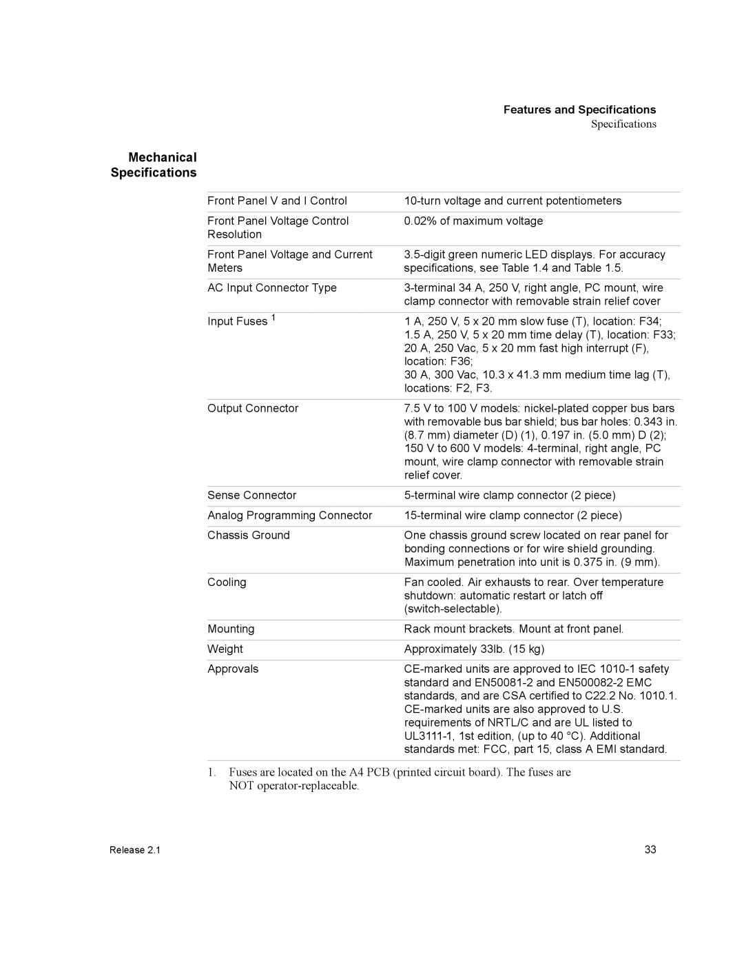
Mechanical
Specifications
Front Panel V and I Control | |
|
|
Front Panel Voltage Control | 0.02% of maximum voltage |
Resolution |
|
|
|
Front Panel Voltage and Current | |
Meters | specifications, see Table 1.4 and Table 1.5. |
|
|
AC Input Connector Type | |
| clamp connector with removable strain relief cover |
|
|
Input Fuses 1 | 1 A, 250 V, 5 x 20 mm slow fuse (T), location: F34; |
| 1.5 A, 250 V, 5 x 20 mm time delay (T), location: F33; |
| 20 A, 250 Vac, 5 x 20 mm fast high interrupt (F), |
| location: F36; |
| 30 A, 300 Vac, 10.3 x 41.3 mm medium time lag (T), |
| locations: F2, F3. |
|
|
Output Connector | 7.5 V to 100 V models: |
| with removable bus bar shield; bus bar holes: 0.343 in. |
| (8.7 mm) diameter (D) (1), 0.197 in. (5.0 mm) D (2); |
| 150 V to 600 V models: |
| mount, wire clamp connector with removable strain |
| relief cover. |
|
|
Sense Connector | |
|
|
Analog Programming Connector | |
|
|
Chassis Ground | One chassis ground screw located on rear panel for |
| bonding connections or for wire shield grounding. |
| Maximum penetration into unit is 0.375 in. (9 mm). |
|
|
Cooling | Fan cooled. Air exhausts to rear. Over temperature |
| shutdown: automatic restart or latch off |
| |
|
|
Mounting | Rack mount brackets. Mount at front panel. |
|
|
Weight | Approximately 33lb. (15 kg) |
|
|
Approvals | |
| standard and |
| standards, and are CSA certified to C22.2 No. 1010.1. |
| |
| requirements of NRTL/C and are UL listed to |
| |
| standards met: FCC, part 15, class A EMI standard. |
1.Fuses are located on the A4 PCB (printed circuit board). The fuses are NOT
Release 2.1 | 33 |