46
YORK INTERNATIONAL
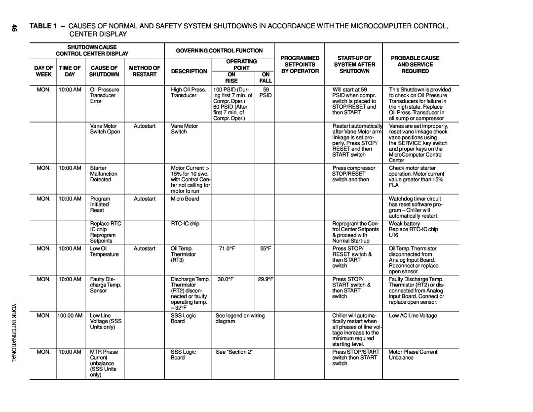
TABLE 1 – CAUSES OF NORMAL AND SAFETY SYSTEM SHUTDOWNS IN ACCORDANCE WITH THE MICROCOMPUTER CONTROL, CENTER DISPLAY
| SHUTDOWN CAUSE |
| GOVERNING CONTROL FUNCTION |
|
|
| |||||
| CONTROL CENTER DISPLAY |
|
|
|
| ||||||
|
|
|
|
|
| PROGRAMMED | PROBABLE CAUSE | ||||
|
|
|
|
|
|
|
|
| |||
|
|
|
|
|
| OPERATING |
| ||||
|
|
|
|
|
|
| SETPOINTS | SYSTEM AFTER | AND SERVICE | ||
DAY OF | TIME OF | CAUSE OF |
| METHOD OF |
| POINT |
| ||||
| DESCRIPTION |
| BY OPERATOR | SHUTDOWN | REQUIRED | ||||||
WEEK | DAY | SHUTDOWN |
| RESTART | ON |
| ON | ||||
|
|
|
|
|
| ||||||
|
|
|
|
|
| RISE |
| FALL |
|
|
|
|
|
|
|
|
|
|
|
|
|
|
|
MON. | 10:00 AM | Oil Pressure |
|
| High Oil Press. | 100 PSID (Dur- |
| 59 |
| Will start at 59 | This Shutdown is provided |
|
| Transducer |
|
| Transducer | ing first 7 min. of |
| PSID |
| PSID when compr. | to check on Oil Pressure |
|
| Error |
|
|
| Compr. Oper.) |
|
|
| switch is placed to | Transducers for failure in |
|
|
|
|
|
| 60 PSID (After |
|
|
| STOP/RESET and | the high state. Replace |
|
|
|
|
|
| first 7 min. of |
|
|
| then START | Oil Press.Transducer in |
|
|
|
|
|
| Compr. Oper.) |
|
|
|
| oil sump or compressor |
|
| Vane Motor |
| Autostart | Vane Motor |
|
|
|
| Restart automatically | Vanes are set improperly, |
|
| Switch Open |
|
| Switch |
|
|
|
| after Vane Motor arm | reset vane linkage check |
|
|
|
|
|
|
|
|
|
| linkage is set pro- | vane positions using |
|
|
|
|
|
|
|
|
|
| perly. Press STOP/ | the SERVICE key switch |
|
|
|
|
|
|
|
|
|
| RESET and then | and proper keys on the |
|
|
|
|
|
|
|
|
|
| START switch | MicroComputer Control |
|
|
|
|
|
|
|
|
|
|
| Center |
MON. | 10:00 AM | Starter |
|
| Motor Current > |
|
|
|
| Press compressor | Check motor starter |
|
| Malfunction |
|
| 15% for 10 swc. |
|
|
|
| STOP/RESET | operation. Motor current |
|
| Detected |
|
| with Control Cen- |
|
|
|
| switch and then | value greater than 15% |
|
|
|
|
| ter not calling for |
|
|
|
|
| FLA |
|
|
|
|
| motor to run |
|
|
|
|
|
|
MON. | 10:00 AM | Program |
| Autostart | Micro Board |
|
|
|
|
| Watchdog timer circuit |
|
| Initiated |
|
|
|
|
|
|
|
| has reset software pro- |
|
| Reset |
|
|
|
|
|
|
|
| gram – Chiller will |
|
|
|
|
|
|
|
|
|
|
| automatically restart. |
|
|
|
|
|
|
|
|
|
|
|
|
|
| Replace RTC |
|
|
|
|
|
| Reprogram the Con- | Weak battery | |
|
| IC chip |
|
|
|
|
|
|
| trol Center Setponts | Replace |
|
| Reprogram |
|
|
|
|
|
|
| & proceed with | U16 |
|
| Setpoints |
|
|
|
|
|
|
| Normal |
|
MON. | 10:00 AM | Low Oil |
| Autostart | Oil Temp. | 71.0°F |
| 55°F |
| Press STOP/ | Oil Temp.Thermistor |
|
| Temperature |
|
| Thermistor |
|
|
|
| RESET switch & | disconnected from |
|
|
|
|
| (RT3) |
|
|
|
| then START | Analog Input Board. |
|
|
|
|
|
|
|
|
|
| switch | Reconnect or replace |
|
|
|
|
|
|
|
|
|
|
| open sensor. |
|
|
|
|
|
|
|
|
|
|
|
|
MON. | 10:00 AM | Faulty Dis- |
|
| Discharge Temp. | 30.0°F |
| 29.9°F |
| Press STOP/ | Faulty Discharge Temp. |
|
| charge Temp. |
|
| Thermistor |
|
|
|
| START switch & | Thermistor (RT2) or dis- |
|
| Sensor |
|
| (RT2) discon- |
|
|
|
| then START | connected from Analog |
|
|
|
|
| nected or faulty |
|
|
|
| switch | Input Board. Connect or |
|
|
|
|
| operating temp. |
|
|
|
|
| replace open sensor. |
|
|
|
|
| = 32°F |
|
|
|
|
|
|
MON. | 100.00 AM | Low Line |
|
| SSS Logic | See legend on wiring |
| Chiller will automa- | Low AC Line Voltage | ||
|
| Voltage (SSS |
|
| Board | diagram |
|
| tically restart when |
| |
|
| Units only) |
|
|
|
|
|
|
| all phases of line vol- |
|
|
|
|
|
|
|
|
|
|
| tage increase to the |
|
|
|
|
|
|
|
|
|
|
| minimum required |
|
|
|
|
|
|
|
|
|
|
| starting level. |
|
|
|
|
|
|
|
|
|
|
|
|
|
MON. | 10:00 AM | MTR Phase |
|
| SSS Logic | See “Section 2” |
|
| Press STOP/START | Motor Phase Current | |
|
| Current |
|
| Board |
|
|
|
| switch then START | Unbalance |
|
| unbalance |
|
|
|
|
|
|
| switch |
|
|
| (SSS Units |
|
|
|
|
|
|
|
|
|
|
| only) |
|
|
|
|
|
|
|
|
|
|
|
|
|
|
|
|
|
|
|
|
|